| Nikon Laser 440 Rangefinder Hack |
 |
 |
 |
 |
 |
 |
 |
| Overview: A tear down and attempt to interface the Nikon laser 400 and 440 laser rangefinders with a computer / microcontroller is documented. The laser 400 and Laser 440 rangefinders are mostly identical with some minor differences. |
|
 |
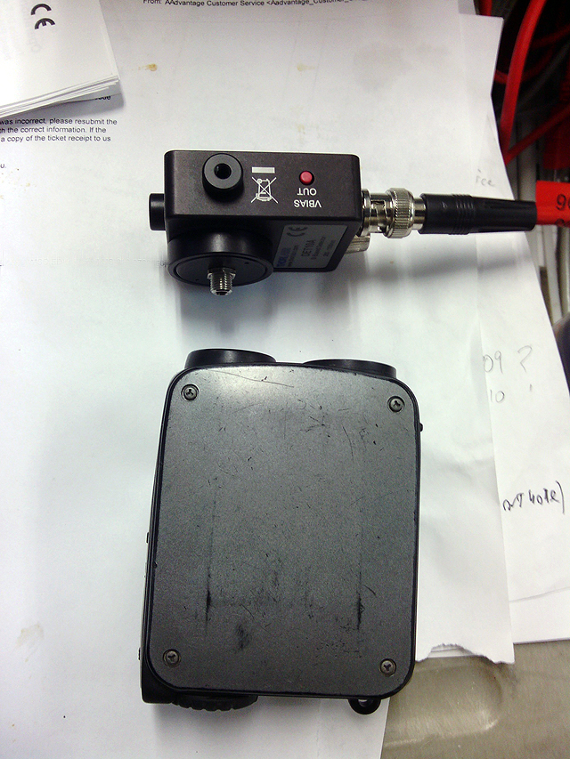
Rangefinder (2/7/2014): Laser 400 Used rangefinder, will not range, possibly has a bad laser A second rangefinder that does range properly was also purchased. |
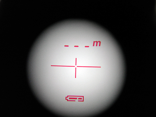 |
Rangefinder (2/7/2014): View through eyepiece |
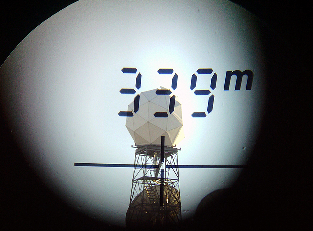 |
Rangefinder (3/2/2014): View through eyepiece |
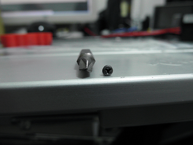 |
Rangefinder (2/7/2014): A triwing bit is needed to open the case. |
 |
Rangefinder (2/7/2014): A DC-DC converter is used to supply power. the rangefinder requires 3V |
 |
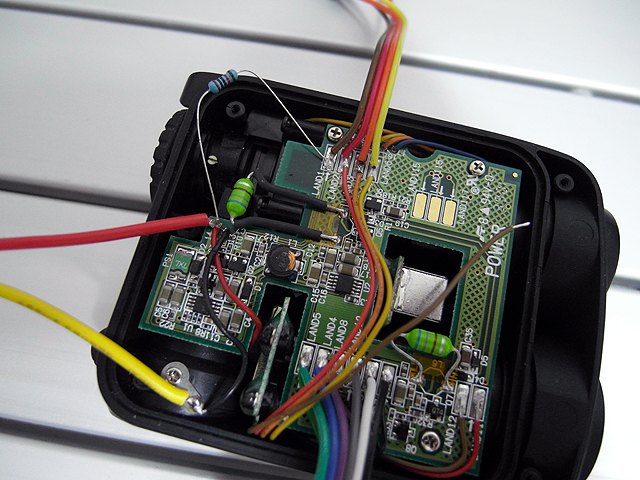
Rangefinder (2/7/2014): Power converter board. Regulates power to controller and provides HV bias to the avalanche photodiode and laser. Top left green inductor is for the Avalanche PD boost converter Bottom right green inductor is for the laser boost converter |
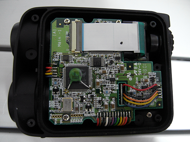 |
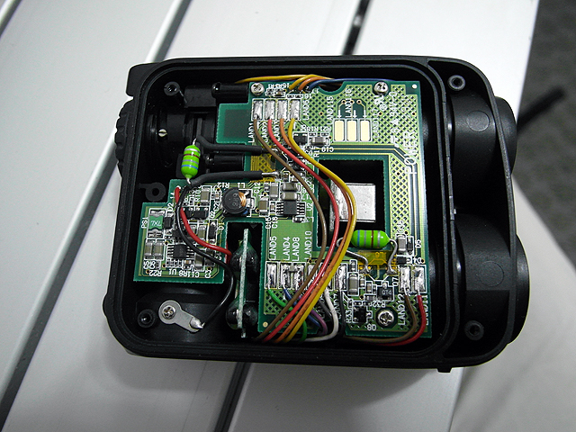
Rangefinder (2/7/2014): Laser 400 Controller board connects to laser transmitter, photodiode and display LCD. |
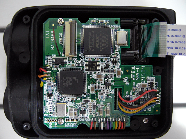 |
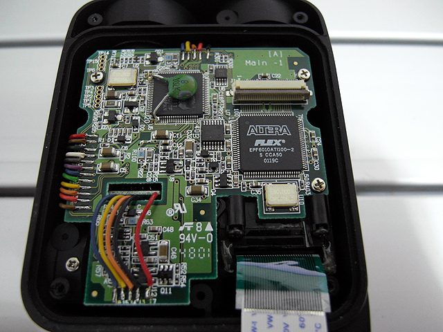
Rangefinder (3/1/2014): Laser 440 Controller board connects to laser transmitter, photodiode and display LCD. |
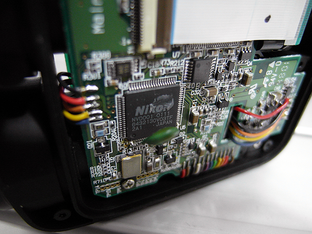 |
Rangefinder (2/7/2014): Laser 400 Nikon NVD001 0111 controller chip. Proprietary / no documentation. |
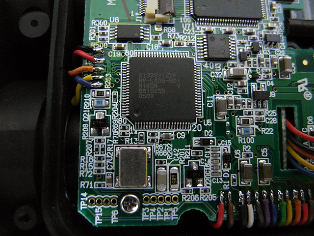 |
Rangefinder (3/2/2014): Laser 440 Nikon NV-L456-H01 controller chip. Proprietary / no documentation. |
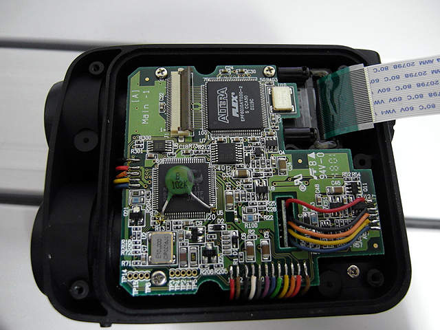 |
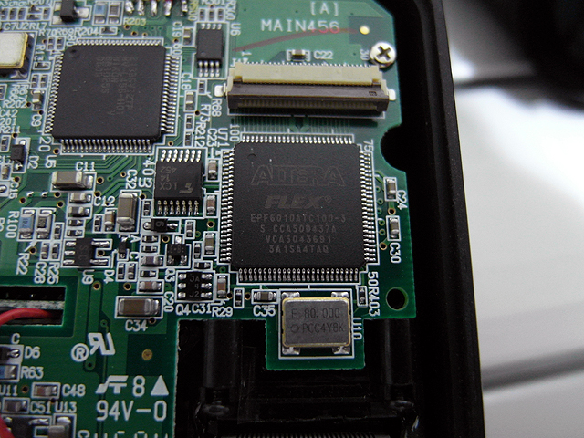
Rangefinder (2/7/2014): Laser 400 Display controller. Altera Flex EPF6010ATI100-2 field programmable gate array. FPGA chip has extremely good documentation. It has a JTAG interface but can't be configured over it. It is configures by a passive serial device on power up. The small chip next to the LCD connector appears similar to an Altera EPC1 configuration chip, but is not connected to the FPGA. It appears to communicate with the Nikon chip with a two wire interface. All interfacing will focus on this chip. The 14 pin SMT chip next to it is a Fairchild LCX14 hex inverter |
 |
Rangefinder (2/7/2014): Laser 440 Display controller. Altera Flex EPF6010ATC100-3 Different speed grade |
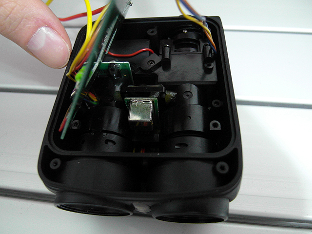 |
Rangefinder (2/7/2014): Laser transmitter |
|
Rangefinder (2/7/2014): Values given are power on steady state, not ranging unless noted. (pwr = when power/range button is pressed) Top row:
Bottom row:
|
|
Rangefinder (2/11/2014): Effect when wires are disconnected Top row:
Bottom row:
|
|
Rangefinder (2/7/2014): Values given are power on steady state, not ranging unless noted. Left (Laser):
Bottom (to power board):
Right (Avalanche PD):
|
|
Rangefinder (2/25/2014): Test points:
|
|
Rangefinder (2/10/2014): Nikon ASIC
ASIC pin 3 to FPGA pin 13,14
|
 |
Rangefinder (2/7/2014): FPGA I/O pins:
LCD:
VCC(3.3v): 6,21,38,54,71,88 GND: 5,20,37,53,70,87 JTAG Interface (not used):
Passive Serial Interface (used for config):
|
 |
Rangefinder (2/10/2014): LCD connector
Logic levels:
|
 |
Rangefinder (2/22/2014): LCD elements are activated by putting them out of phase with the common connection that is selected. This is tested with a 100Hz square wave generator with complementary outputs.
|
 |
Rangefinder (2/22/2014): Notation is 7seg <R(right), C(center), L(left)>, for which 7seg digit and <B(bottom), M(middle), T(top)><R(right), C(center), L(left)> for 7seg digit elements Pins 1 and 5 are out of phase(probably common) with all other pins when all segments are on during power up. LCD connector pinout
|
 |
Rangefinder (2/22/2014): Power shutdown sequence: On power board
|
 |
Rangefinder (2/22/2014): Power control board test Removing the brown wire and connecting a 10k resistor between the connector pad and battery+ causes the rangefinder to power up as soon as power is applied to the power terminals, and locks the rangefinder in a powered on state. All the rangefinder controls and buttons work properly, however after the 8 second inactivity delay when the rangefinder usually shuts down, it will no longer respond to button inputs. The LCD display remains on though. The brown wire is bootstrapped high through the power button and is pulled high by the ASIC to keep the power on after the power button is released. It is pulled low to shut off rangefinder power. |
 |
Rangefinder (2/25/2014): Laser output testing with a thorlabs DET10A high speed silicon detector. |
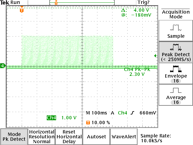 |
Rangefinder (2/25/2014): Laser pulse burst lasts 600ms |
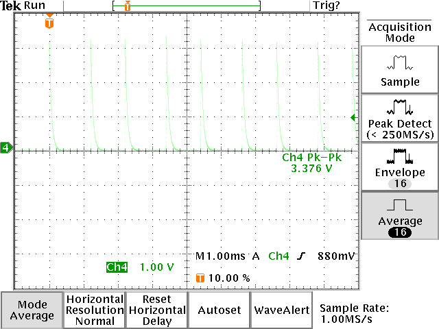 |
Rangefinder (2/25/2014): Pulses are 1.2ms apart, this equates to 500 pulses per range measurement. This measurement is with a 1K resistor across diode output(RC decay time in pulse trace instead of proper time resolution with matched load, but greater amplitude) Based on logic analyzer traces it appears the controller shifts the timing between the laser pulse and the avalanche PD pulse and probably looks to see if the pulse turns on. In essence it is iteratively looking at all 500 one meter increments between the rangefinder and the maximum range and determining if something is there. A binary search would have been a much better way to find the target and could range ~50 times faster. |
 |
Rangefinder (2/25/2014): Pulse with matched 50ohm load. Average of 500 pulses. Each pulse is ~20ns wide. |
 |
Rangefinder (2/25/2014): FPGA JTAG interface attempt. This will require !ltera Quartus 9.0 SP2 web version, which is the last version to support the FLEX6000 FPGA which has entered legacy status. |
 |
Rangefinder (2/25/2014): So far attempts to connect with the JTAG interface have been unsuccessful probably due to a poor connection between the ribbon cable header and the FPGA pins. When connected this would allow uploading of the SOF configuration file from the FPGA as a backup if the code is modified. Engineers at !ltera say it is impossible to decompile a SOF file back into VHDL but some coders on the internet say that it is possible. It is possible to upload the SOF file and download it onto other chips though. This chip has a JTAG interface but can't be configured over it. It is configures by a passive serial device on power up. The small chip next to the LCD connector appears similar to an Altera EPC1 configuration chip, but is not connected to the FPGA. |
 |
Rangefinder (2/25/2014): ASIC serial data interface:
|
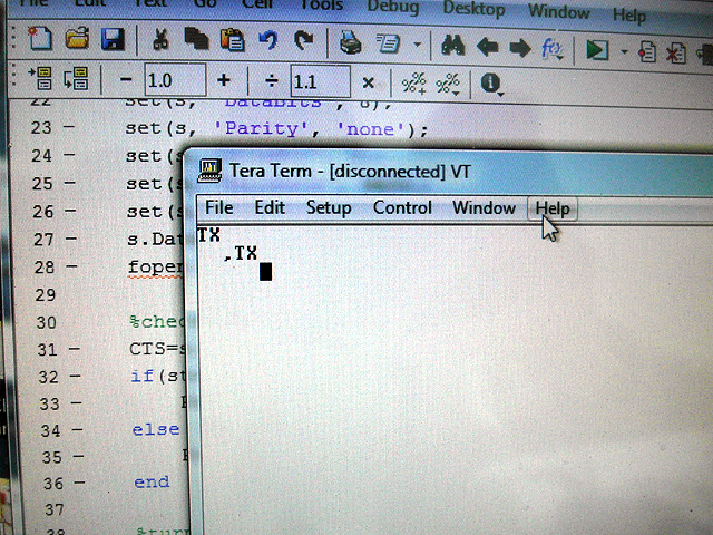 |
Rangefinder (2/25/2014): ASIC transmits "TX<LF>" on power up. No <CR>, just <LF> ignore the comma, that's just a power cycling glitch. |
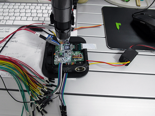 |
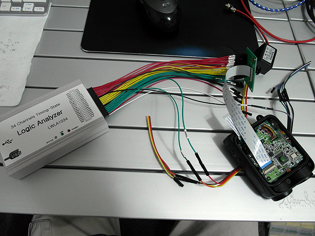
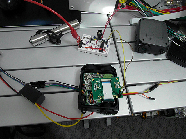
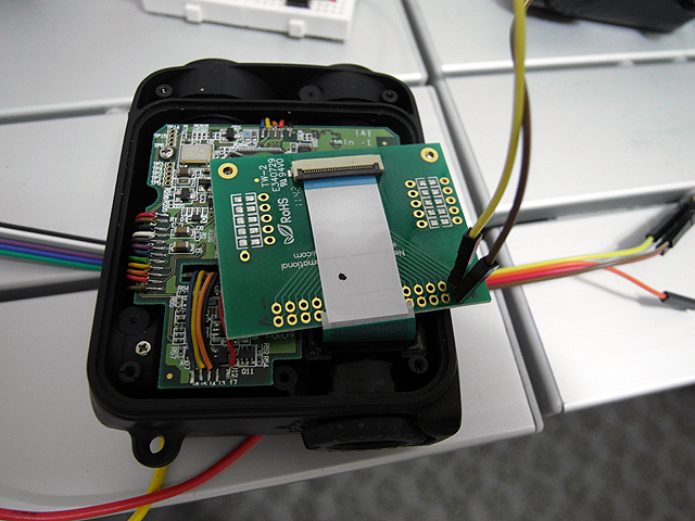
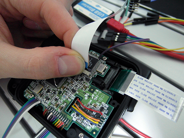
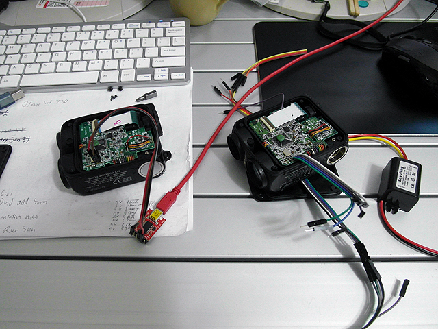
Rangefinder (3/2/2014): Passive serial data interface Nano clips and USB microscope for clip placement on 0.5mm pitch pins Surface mount nano test clips connecting logic analyser to passive serial config pins |
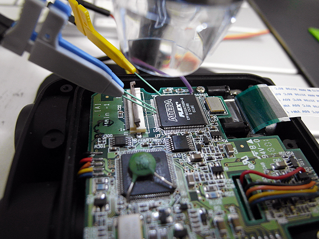 |
Rangefinder (3/2/2014): Nano clips attached |
 |
Rangefinder (3/2/2014): Nano clips attached to passive serial pins |
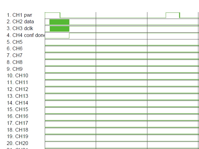 |
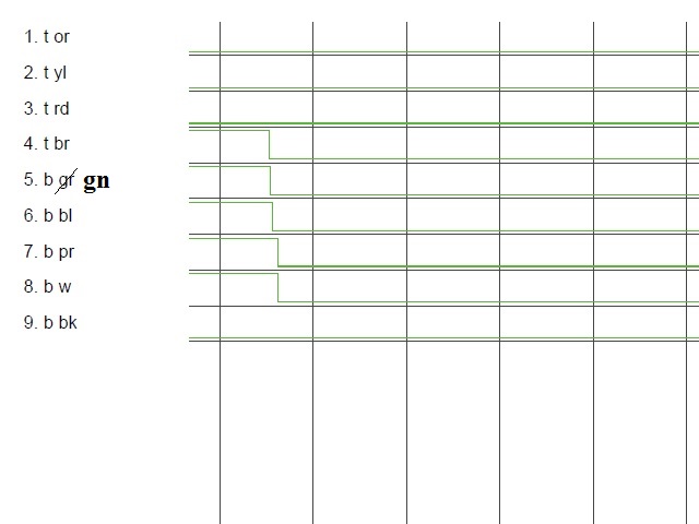
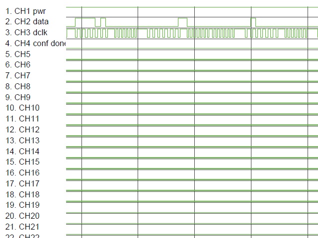
Rangefinder (3/2/2014): Passive serial data capture Successful interfacing with passive serial data stream. Unfortunately it is generated by ASIC, which can not be reconfigured like an external configuration device. Possibilities for computer interfacing are now hacking the TTL serial on the ASIC, decoding the LCD signals, or intercepting data between the ASIC and FPGA. Passive Serial Interface:
|
 |
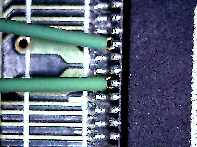
Rangefinder (3/2/2014): Passive serial data capture zoomed in |
Rangefinder (3/2/2014):
|
|
By attempting to reproduce any experiments or devices listed on this domain in part or in whole, you agree to hold me harmless against any lawsuit or liability. Copyright © 1998 - 2005 by Andrew Seltzman. All rights reserved. |
|
| Contact me at: admin@rtftechnologies.org | |