| Ignition Coil Driver |
 |
 |
 |
 |
 |
 |
 |
| Overview: This design uses a 555 timer and three 2n3055 switching transistors to provide a variable frequency, variable voltage input to an automotive ignition coil. Normal output is 25kV when run at 12v input and at the coil's resonant frequency (8kHz). Increasing the voltage output to about 50kV is possible if the input voltage is increased to 34v, however this risks burning out the switching transistors when the system is operated for an extended time.
|
|
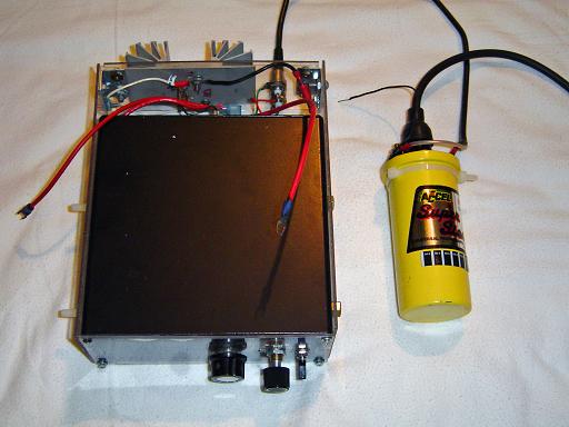 |
Coil Driver: At maximum output the coil will generate 3-5cm plasma arcs. |
 |
Electrical Diagram: Capacitors: rated at 50v Resistors: 1/2w, 5% tolerance Output frequency to the coil is controlled by VR1, output voltage is controlled by VR2. V+ is connected to pin 3 on the 5v regulator. |
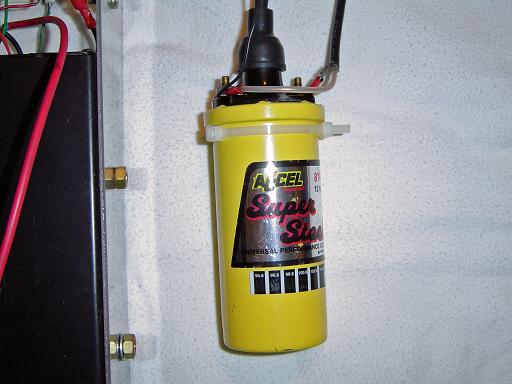 |
Ignition Coil: Accel ignition coil, resonant frequency 8kHz |
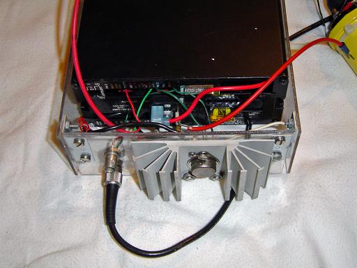 |
Heat sink: One transistor is mounted to the heat sink, the others are mounted to the bottom of the case. |
By attempting to reproduce any experiments or devices listed on this domain in part or in whole, you agree to hold me harmless against any lawsuit or liability. Copyright © 1998 - 2005 by Andrew Seltzman. All rights reserved. |
|
| Contact me at: admin@rtftechnologies.org | |