| Neon Sign Transformer Center Tap Removal |
 |
 |
 |
 |
 |
 |
 |
| Overview: Neon sign transformers are used as a source of high voltage power for many HV experiments, however the maximum voltage that can be extracted from the secondary with respect to ground is only half of the voltage rating of the transformer. This is due to a neon sign transformer's center tap on the secondary windings of the transformer. The mid point of the secondary is grounded so that the transformer will supply the rated voltage at the two outputs as a differential(one is +- 1/2Vs, other is -+1/2Vs). This prevents experimentation where you want to use the full potential of the transformer with respect to ground. Since the center tap is connected to the transformers metal case, disconnecting the ground from the transformer case will allow one side of the transformer to reach the full potential while the other is grounded, however the case will float at several kV, so this is not recommended. A second slightly more difficult, but considerably safer option is to disconnect the center tap. The procedure for this modification is documented here. The transformer modified here is an Allanson 12,000v 30mA Uni Tran model NST. |
|
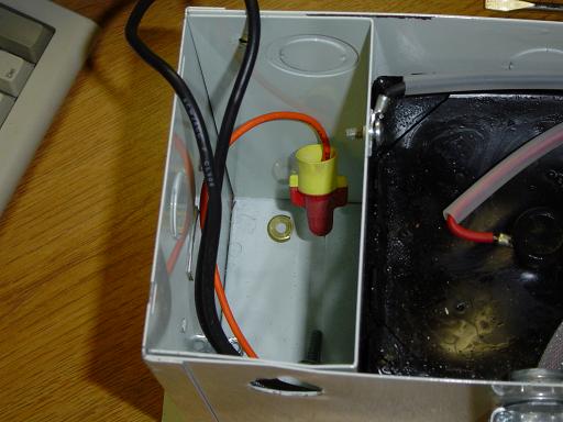 |
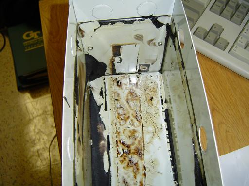
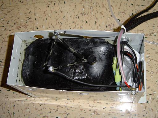
Wiring Box: Wiring box for the nst. The plate separating the wiring box from the nst is held in plane only by the case grounding screw (removed in picture) and the tar the transformer in encapsulated in. |
 |
Plate Removal: The sides of the plate are bent inward and the plate is pulled off the tar. The wires slide through the grommet in the wall. |
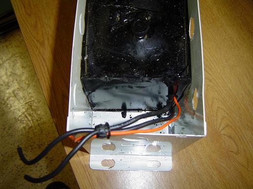 |
Plate Removed: The wiring box plate is removed leaving only the nst core in the case. |
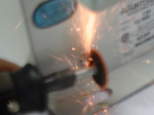 |
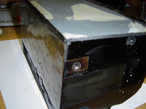
Slotting Tap Screw: The tap screw connecting the center tap anchors the core to the case. The screw has a square security head. A dremel is used to cut a slot in the screw so it can be removed. |
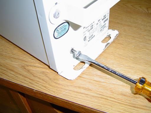 |
Removing Tap Screw: The screw is then removed with a slotted screwdriver. |
 |
Transformer Case: The inside of the case is coated with tar. This is chiseled off to allow the core to be easily re inserted. |
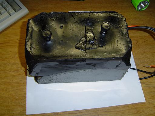 |
Transformer Core: The core of the nst has plastic sheets attached to it's sides. |
 |
Center Tap Location: Center tap of the nst core. This is insulated before the core is reinserted into the case. |
 |
HV Arc: One terminal is grounded and a 15,000v arc is generated. This is at 150v on the primary. If one terminal is grounded and no arc is drawn from the nst, no arcing will occur between the primary and secondary. |
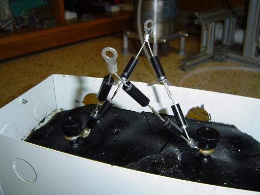 |
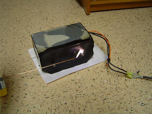
Rectifier: The transformer core is encased in two layers of FedEx bubble wrap packing to insulate the center tap from the case and is then reinstalled. A bridge rectifier is attached to both terminals of the secondary to provide a DC output. |
 |
Untapped Transformer: One side of the rectifier is grounded. The nst will now supply -15,000v. |
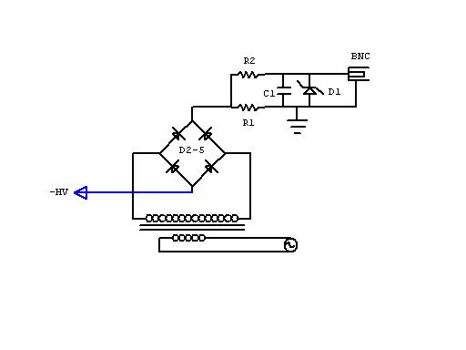 |
Current Monitor Diagram:
Current monitor provides a filtered 0.1V per ma. Zener diode protects external monitoring equipment from surges. |
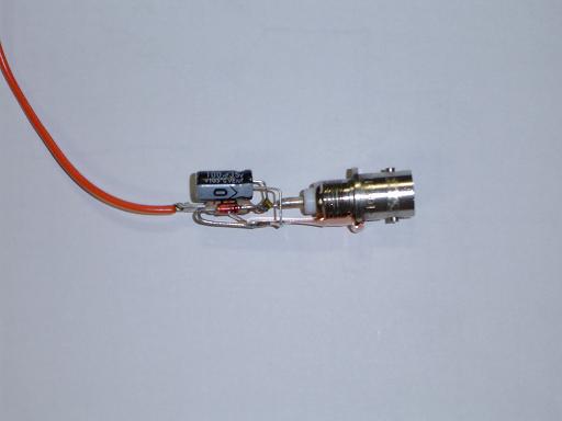 |
Current Monitor: Current monitor is built onto a BNC connector |
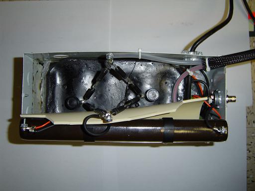 |
Complete Transformer: Untapped, rectified neon sign transformer with current monitoring. |
|
|
By attempting to reproduce any experiments or devices listed on this domain in part or in whole, you agree to hold me harmless against any lawsuit or liability. Copyright © 1998 - 2005 by Andrew Seltzman. All rights reserved. |
|
| Contact me at: admin@rtftechnologies.org | |