| Edwards EXT 70 Turbo pump Repair |
 |
 |
 |
 |
 |
 |
 |
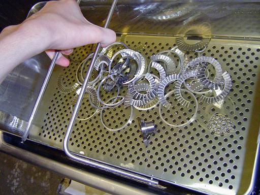
| Overview: Documentation of the cleaning and repair of an Edwards EXT70 turbo molecular vacuum pump. Modification of turbo pump to replace damaged magnetic bearing with ceramic hybrid bearing. The modification of replacing the rotor magnets with a hybrid bearing ended up not working. The pump would vibrate before it reached full speed, probably due to balance issues. Other EXT-70 pumps were repaired by replacing cracked stator magnets and leaving the cracked rotor magnets in place. Cracked rotor magnets may not cause any problems (for small radial cracks with no chips missing) since they are held in place by the top press fit aluminum ring and the rotor casing. Cracked stator magnets should be replaced if possible, either from other EXT70 pumps or with custom replacements. The magnet specs are: Ring magnet 1 (for rotor): |
|
|
|
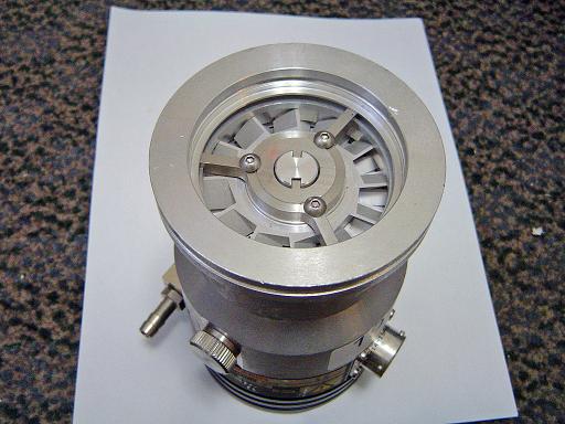
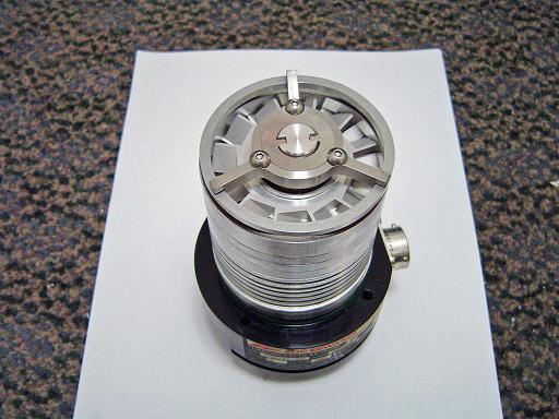
EXT 70 Turbo pump (1/02/2009) Used EXT 70 turbo pump with cracked magnetic bearings and sticking rotors. |
 |
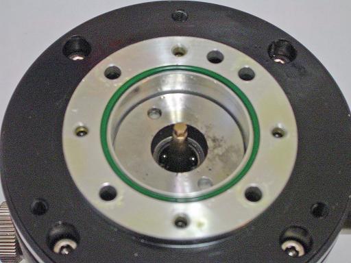
Bearing oil cartridge (1/02/2009) Contains oil that lubricated bottom ceramic bearing. |
|
|
Bearing oil cartridge (1/02/2009) Fabric inserts are saturated with oil. Oil is transferred from fabric inserts to bearing nut by the two triangular tabs. Centripetal force moves the oil upward along the conical nut providing a continuous flow of oil across the bearing. |
 |
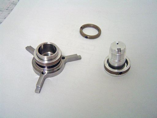
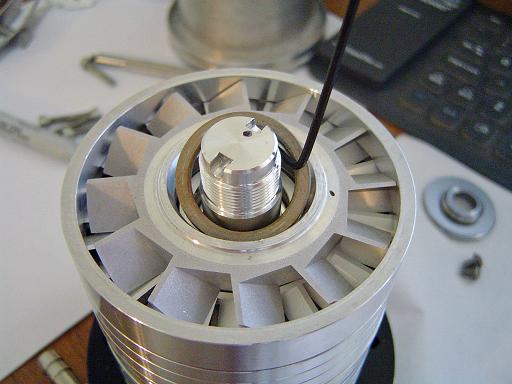
Bearing nut (1/02/2009) Holds rotor in correct vertical position. |
|
|
Bearing (1/02/2009) Hybrid ceramic bearing. Bearing race fell off bearing, probably during operation causing vibration of the rotor assembly causing rotor shaft to crash into oil reservoir bushing and melt. |
 |
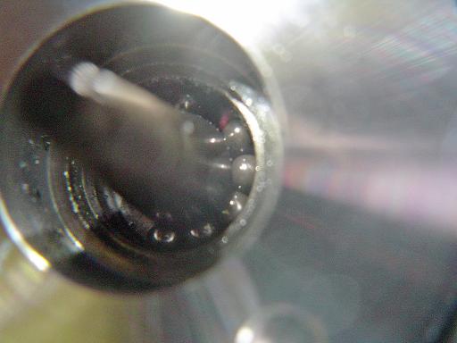
Bearing race (1/02/2009) Bearing race covered in burnt oil. |
|
|
Rotor lock (1/02/2009) Rotor is locked in place by inserting 3 rubberized file handles through the pump blades and against the magnetic bearing holder. |
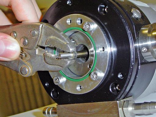 |
Rotor nut removal (1/02/2009) The head of an allen screw is used to remove the rotor nut. Nut has right hand thread. |
|
|
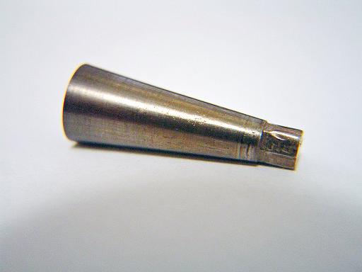
Rotor nut (1/02/2009)
|
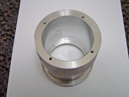 |
Pump casing (1/02/2009) Aluminum body of turbo pump. |
|
|
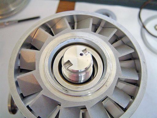
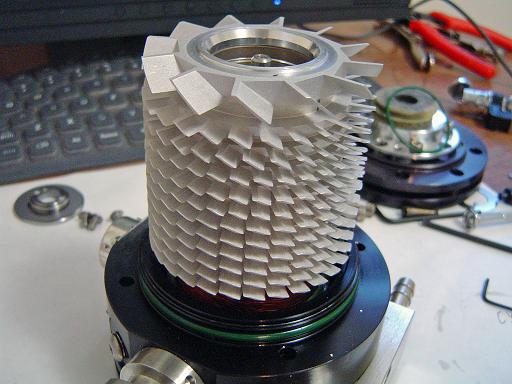
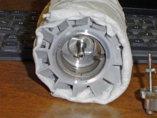
Rotor assembly (1/02/2009) Rotor, magnetic bearing, and stator stack. |
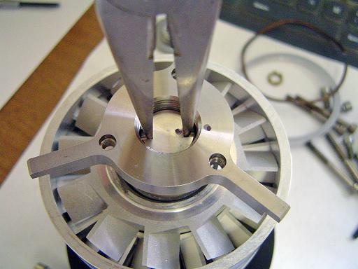 |
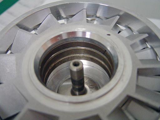
Magnetic bearing removal (1/02/2009) Compression stack unscrewed. |
|
|
Magnetic bearing removal (1/02/2009) Bearing consists of 3 magnet rings. |
 |
Magnetic bearing removal (1/02/2009) Magnet rings are removed with allen key. |
|
|
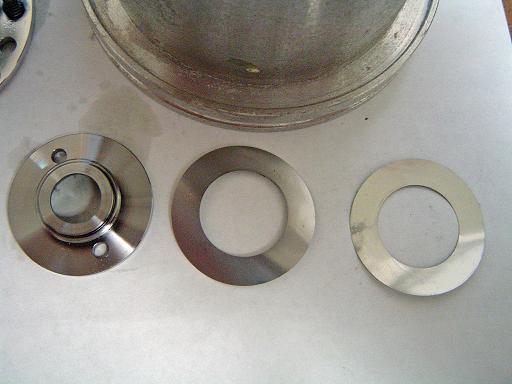
Magnetic bearing removal (1/02/2009) Removed magnetic bearing. Stator magnets are 27mm OD, 21mm ID, 4mm thick. |
 |
Pump rotor (1/02/2009)
|
|
|
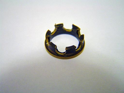
Cracked magnetic bearing (1/02/2009) Cracked magnet ring. |
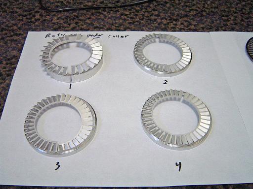 |
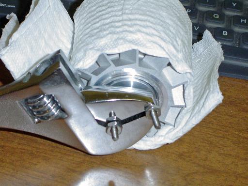
Stator blades (1/02/2009) Stator blades are separated by aluminum rings. Blade rings are assembled as two half rings. |
|
|
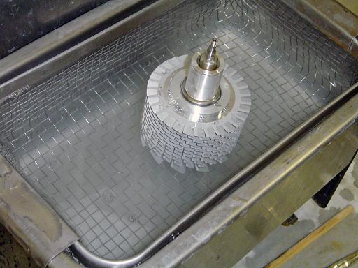
Stator cleaning (1/02/2009) Stators are cleaned in a sonic bath. |
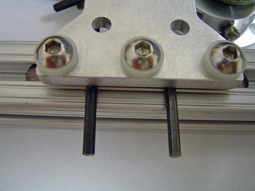 |
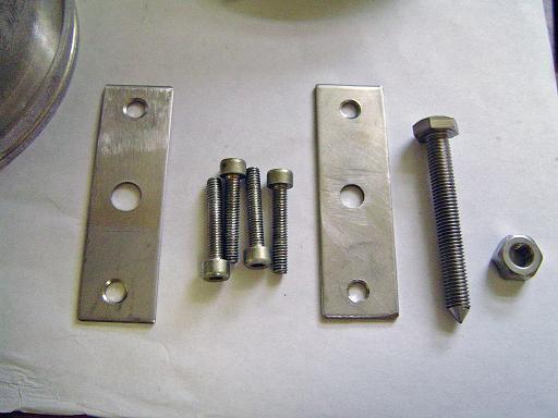
Bottom bearing spanner (1/02/2009) Two allen keys are bolted to an aluminum bar for use as a spanner wrench. |
|
|
Bottom bearing removal (1/02/2009) Bearing compression disk is removed with the spanner tool. |
 |
Bearing compression disk. (1/02/2009) Compression disk and two shims |
|
|
Bottom bearing (1/02/2009)
|
 |
Bottom bearing puller (1/02/2009) Since the rotor shaft collided with the bushing and melted together, a removal tool is required to crack the fused metal. |
|
|
Bottom bearing removal tool (1/02/2009) Screws hold cross to pump body while bolt pushes on the shaft. |
 |
Rotor removed (1/02/2009) Rotor and oil reservoir. |
|
|
Bushing (1/02/2009) Burnt rubber and oil around bushing. |
 |
Bushing and bearing (1/02/2009) Burnt oil in bearing. |
|
|
Bushing (1/02/2009) Bushing was melted in the location where the rotor shaft collided with it while spinning at 90000 rpm. |
 |
Rotor shaft (1/02/2009) Rotor shaft was melted when it collided with the bushing. |
|
|
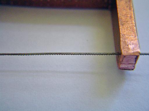
Micro hack saw (1/02/2009) A micro hack saw was built to re-cut the threads on the rotor which were deformed by the bearing puller. |
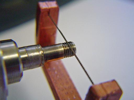 |
Rotor shaft (1/02/2009) Threads are repaired with micro hack saw. |
|
|
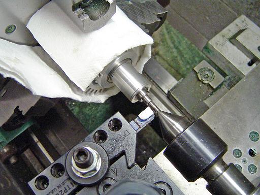
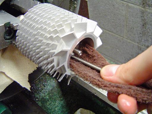
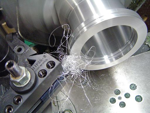
Rotor shaft repair (1/02/2009) Rotor is gripped in a 3 jaw chuck by the blades with paper towel cushioning to prevent damage. A live center is used to stabilize the rotor shaft. Rotor shaft is cut down to size to remove molten metal globs on the surface. |
|
|
Magnetic bearing ring puller (1/02/2009) Magnet rings are held in by a press fit aluminum ring. A tool is constructed to pull the ring out of the rotor. Four cup point allen screws dig into the rings inner surface and attach it to the removal tool. A pair of screws is then used to pull both the extractor, and the ring out of the rotor assembly. |
 |
Magnetic bearing ring puller (1/02/2009) A wrench is used to twist and pull the extractor until the ring is removed. |
|
|
Magnetic bearing ring puller (1/02/2009) Ring and removal tool |
 |
Magnet rings (1/02/2009) Cracked magnet rings are removed by cracking them with a punch and removing the fragments. Rotor magnets are 34mm OD, 28mm ID, 4mm thick. |
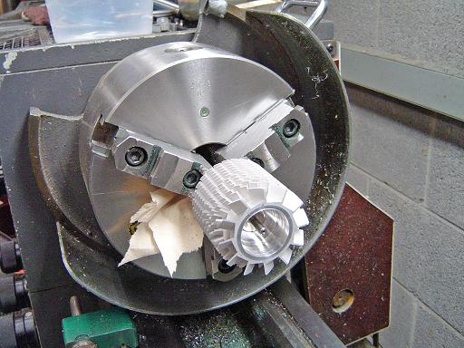 |
Rotor cleaning (1/02/2009) Rotor is held in lathe chuck by motor magnet. |
|
|
Rotor cleaning (1/02/2009) Magnet ring area is cleaned with scotch brite. |
 |
Rotor cleaning (1/02/2009) Rotor is cleaned in sonic bath. |
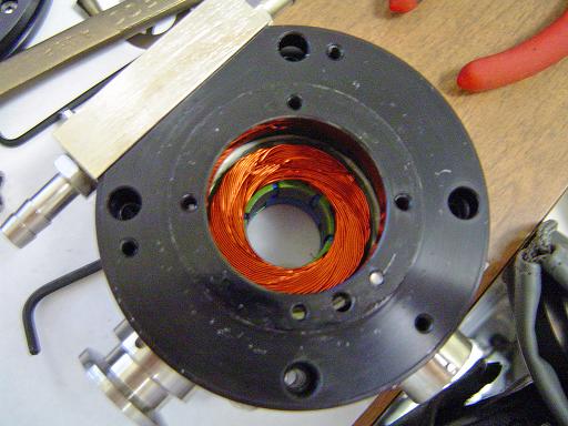 |
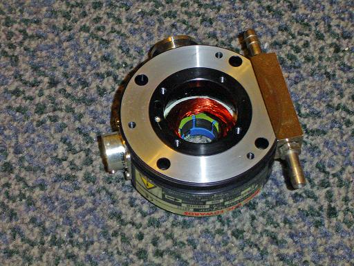
Motor (1/02/2009) Brush less motor in base of pump. |
|
|
Motor (1/02/2009) O-ring surface was damaged during removal of the rotor and was refaced on lathe. |
|
|
Motor (1/02/2009) Resurfaced motor. |
 |
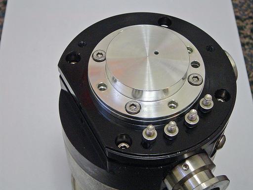
Pump case cleaning(1/02/2009) Flange refaced, pump body polished. |
|
|
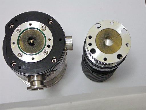
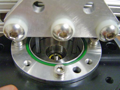
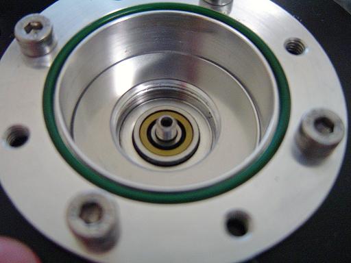
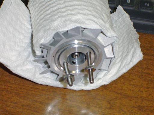
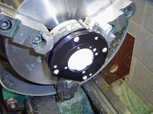
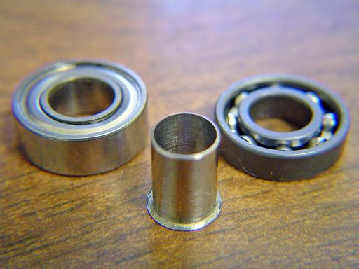
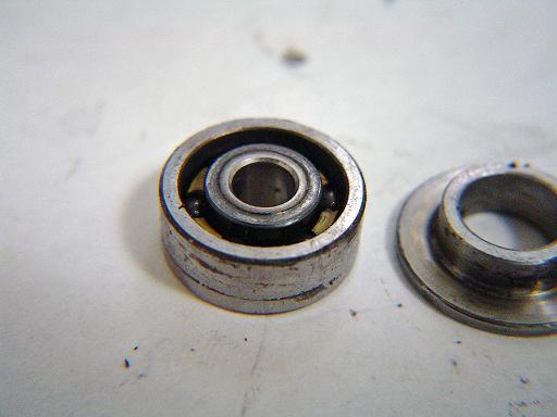
Top bearing (1/02/2009) New ceramic hybrid bearing(left) to replace the damaged magnetic bearing assembly. Also shown is an adaptor bushing to allow use of the bearing on the rotor shaft and the original safety bearing. New bearing is permanently lubricated and rated at 100k rpm continuous use. |
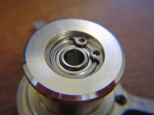 |
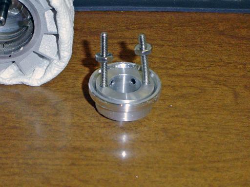
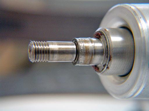
Top bearing (1/02/2009) Bearing holder was turned on the lathe to increase the bearing mount depth to allow use of the thicker hybrid bearing. Bushing is shown installed in assembly. |
 |
Rotor spring (1/02/2009) Precision spring on rotor shaft. Spring holds bushing in bearing and pre lodes bottom bearing. |
|
|
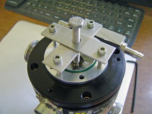
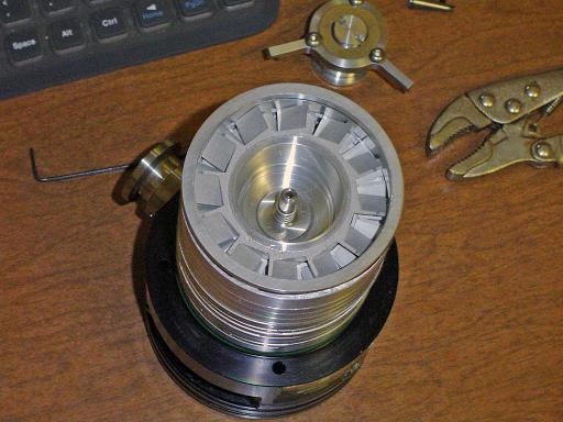
Rotor assembly (1/02/2009) Turbo pump is assembled with bearing and oil reservoir salvaged from another EXT 70 pump. Cleaned stators are installed. |
|
|
Assembled pump (1/02/2009) Pump body and base are attached. Pump rotor spins freely. |
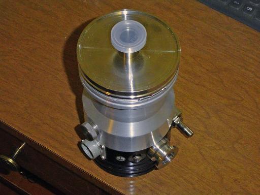 |
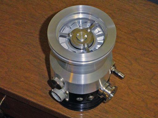
Assembled pump (1/02/2009) ISO63 to NW16 adaptor is installed on pump. |
|
|
|
|
|
|
By attempting to reproduce any experiments or devices listed on this domain in part or in whole, you agree to hold me harmless against any lawsuit or liability. Copyright © 1998 - 2005 by Andrew Seltzman. All rights reserved. |
|
| Contact me at: admin@rtftechnologies.org | |