| Powered Exoskeleton Hydraulic Component Testing |
 |
 |
 |
 |
 |
 |
 |
| Hydraulically powered exoskeleton. Hydraulic component testing | |
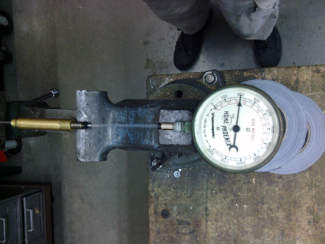 |
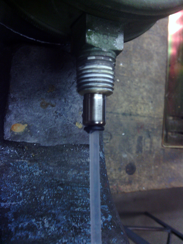
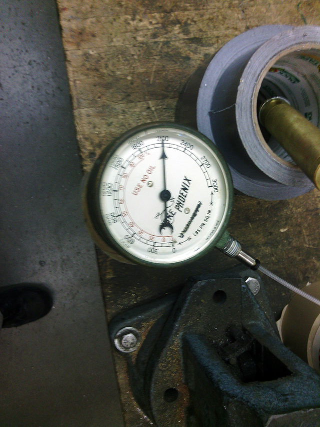
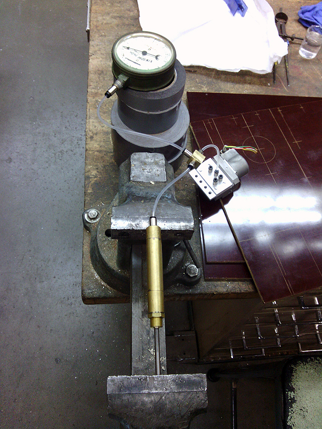
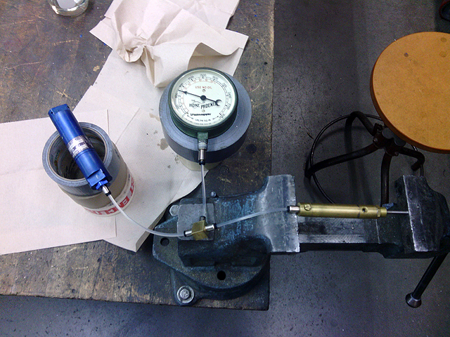
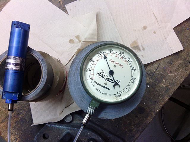
Component Identification (10/18/2013) Hydrostatic testing setup: Small clippard micromatic cylinder filled with water compressed in vice, and pressure gauge. |
 |
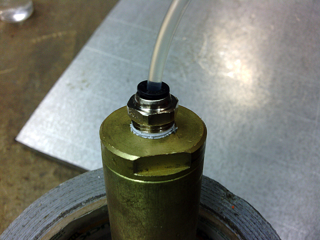
Component Identification (10/18/2013) Legris connectors of the older style with brass tube collet (1/8 hose to 10-32 thread) OK at 1800psi |
 |
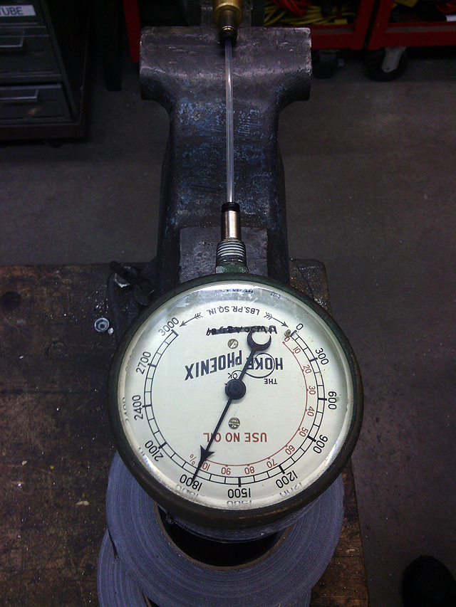
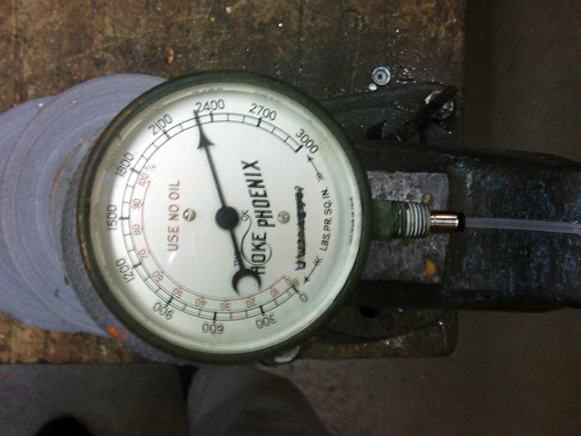
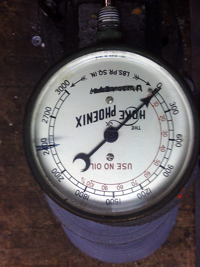
Component Identification (10/18/2013) Failure between 1800 to >2400psi, varying from connector to connector based on manufacturing variations. |
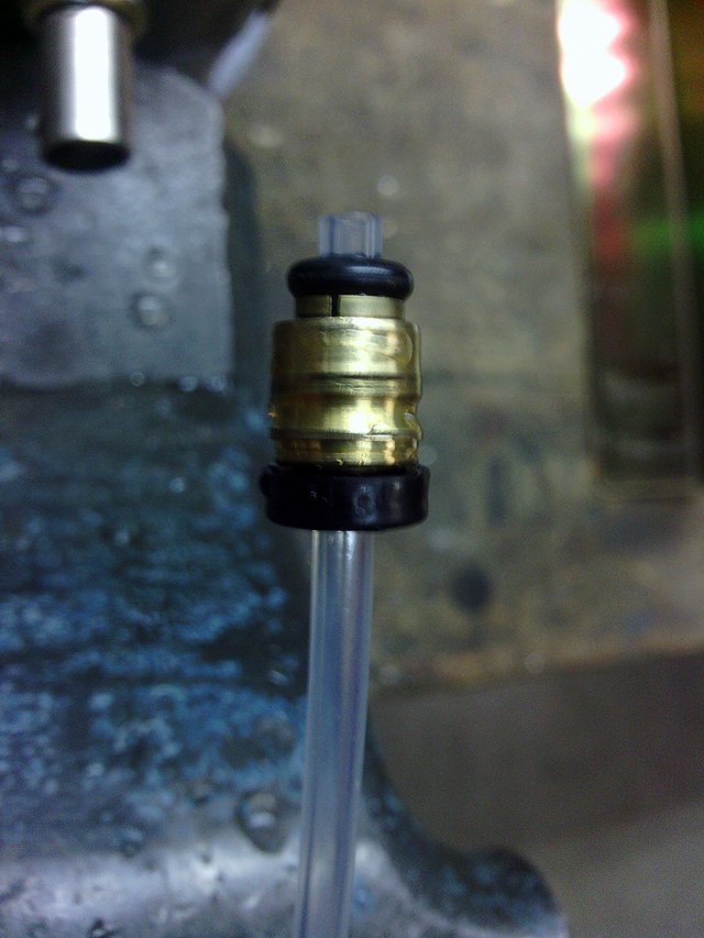 |
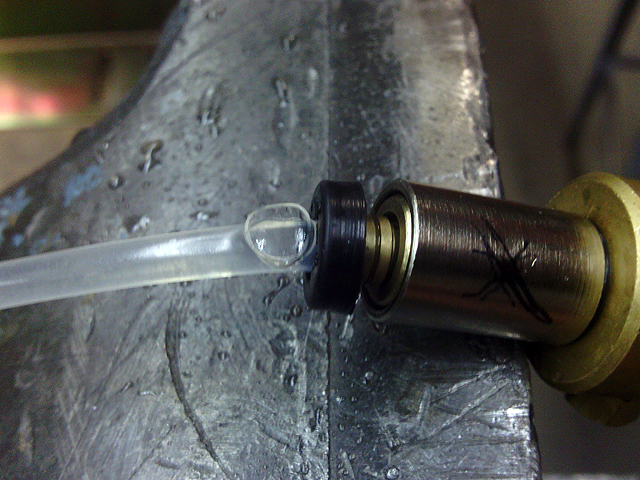
Component Identification (10/18/2013) Failure by brass collet blowing out of case. |
 |
Component Identification (10/18/2013) Legris connectors of the newer style with stainless pronged tube grippers and crimped end. (1/8 hose to 10-32 thread) |
 |
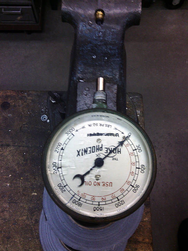
Component Identification (10/18/2013) Legris connectors of the newer style (Legris 3171 53 20) OK at >2400psi. Connector begins to damage tube over 2400psi as the grippers dig into the tube surface but connector will not fail. Sometimes tube is difficult or impossible to remove if the surface is damaged by grippers. All connectors tested of this style consistently achieve this result. |
 |
Component Identification (10/18/2013) Failure of tube at 2400psi by tube rupture at bends in tube. Straight tube will survive to 2700psi. Tube is FreelinWade (1E-280-10) nylon 11, 1/8"OD, 0.073"ID, (Rockwell R108) hardness McMaster P/N 9685T1 |
 |
Component Identification (10/18/2013) Tube fails by bursting |
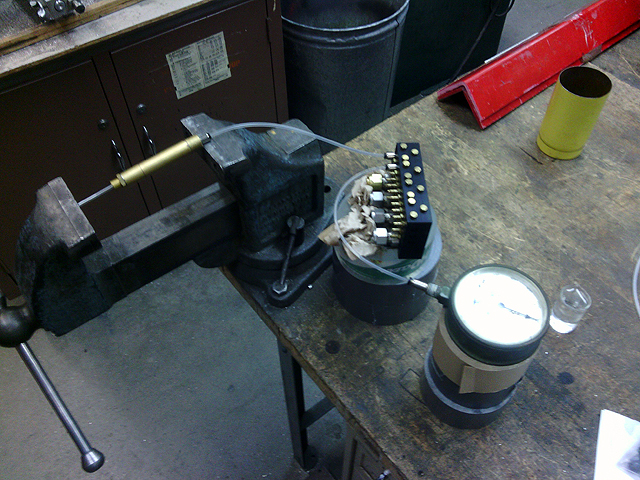 |
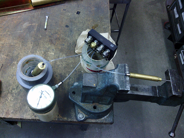
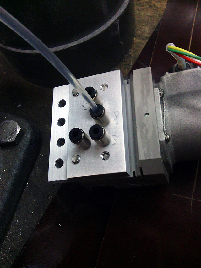
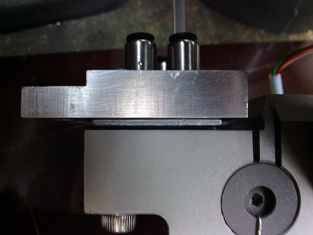
Component Identification (10/18/2013) Testing of distribution manifold block |
 |
Component Identification (10/18/2013) Block OK at 2000psi |
 |
Component Identification (10/18/2013) Legris fitting (1/8npt to 1/8 tube) and clippard 7D/7SD series cylinder |
 |
Component Identification (10/18/2013) Testing of clippard 7D/7SD series cylinder |
 |
Component Identification (10/18/2013) Cylinder OK at 2100psi |
 |
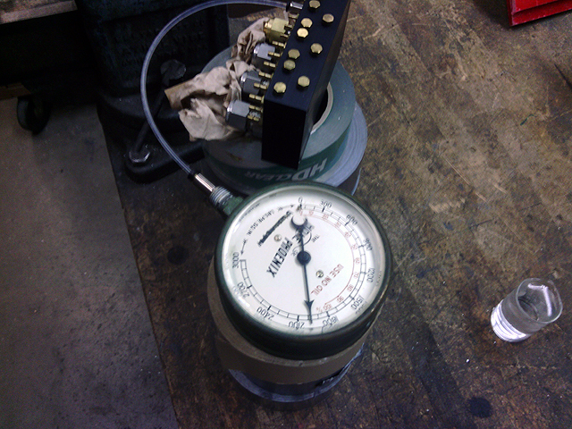
Component Identification (10/18/2013) Hydraulic valve block prototype under test |
 |
Component Identification (10/18/2013) Hydraulic valve block prototype with blank off block. |
 |
Component Identification (10/18/2013) Hydraulic valve block prototype OK at 2100psi |
 |
Component Identification (10/18/2013) Testing of relief valve |
 |
Component Identification (10/18/2013) Valve set to open at 1000psi |
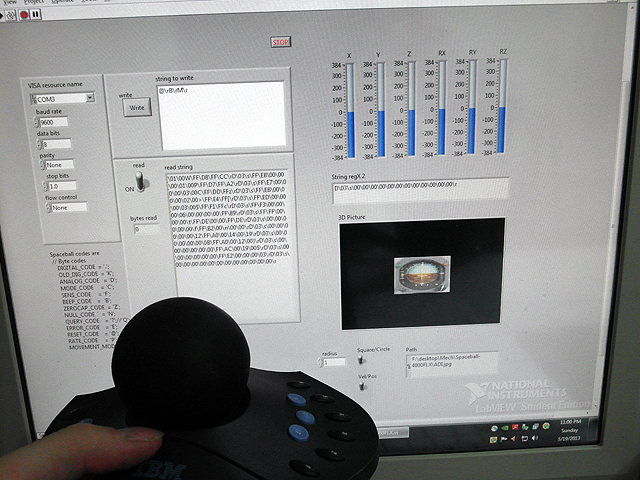 |
Component Identification (10/18/2013) Space ball 6DOF controller data being read in labview |
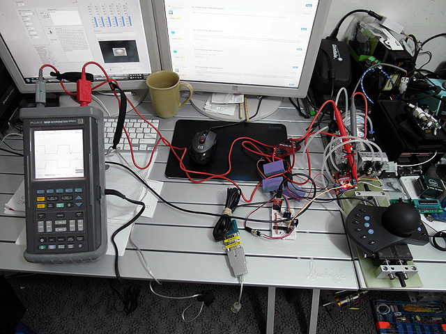 |
Component Identification (10/18/2013) Servo valve testing setup: spaceball mounted on hydraulic stage reads user force and torque and sends data to computer. Computer forwards data to microcontroller which synthesizes square wave PWM to servo valve through an H-bridge to control valve current. Valve actuates stage. |
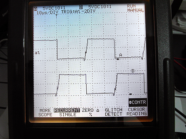 |
Component Identification (10/18/2013) PWM waveform from microcontroller |
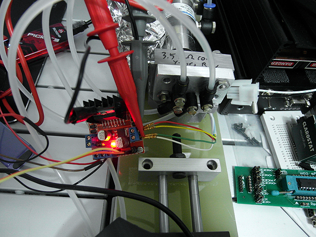 |
Component Identification (10/18/2013) H-bridge connected to 18v controlling current through valve |
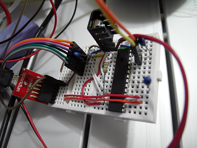 |
Component Identification (10/18/2013) dsPIC microcontroller |
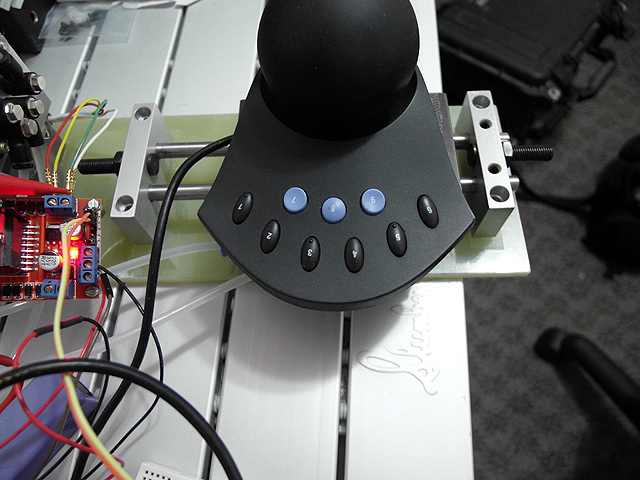 |
Component Identification (10/18/2013) Spaceball on hydraulic stage |
|
Component Identification (10/18/2013) Testing video of valve controller. |
Component Identification (10/18/2013)
|
|
Component Identification (10/18/2013)
|
|
Component Identification (10/18/2013)
|
|
|
|
|
|
By attempting to reproduce any experiments or devices listed on this domain in part or in whole, you agree to hold me harmless against any lawsuit or liability. Copyright © 1998 - 2013 by Andrew Seltzman. All rights reserved. |
|
| Contact me at: admin@rtftechnologies.org | |