| Sargent-Welch 3102 Turbomolecular Vacuum Pump Repair |
 |
 |
 |
 |
 |
 |
 |
| Overview: As part of my work with the national undergraduate fellowship in plasma physics in the summer of 2007, a welch 3102 turbo pump was repaired for use on a plasma physics experiment at University of Wisconsin Madison. |
|
Turbo pump documentation |
|
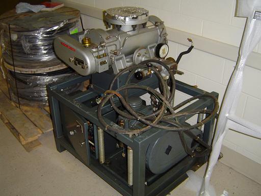 |
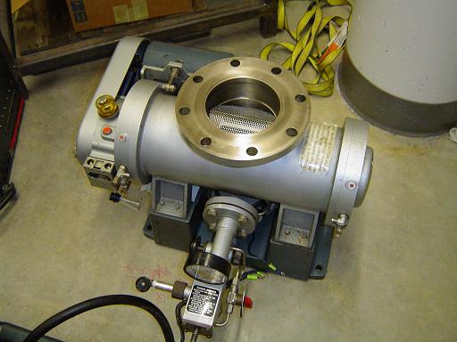
Sargent-Welch 3102 turbo pump (8/25/2007) Turbo pump station containing welch 3102 turbo pump and welch 1397 backing pump |
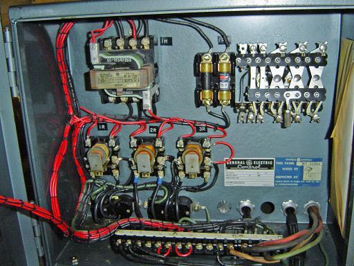 |
Turbo pump control (8/25/2007) The turbo pump is driven directly off of the 208V 3ph mains at 60Hz. The only function of the control box is to interlock the turbo so that it can only be run when the backing pump is on. |
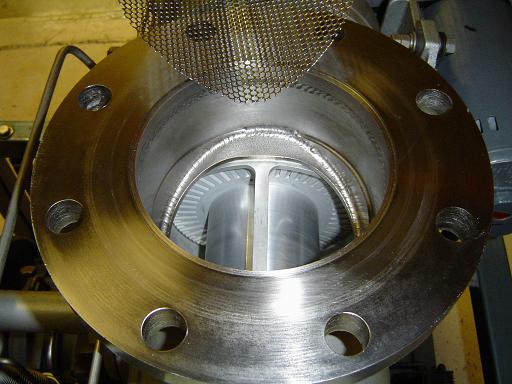 |
Inlet (8/25/2007) Inlet is 11" ASA flange and contains debris screen. |
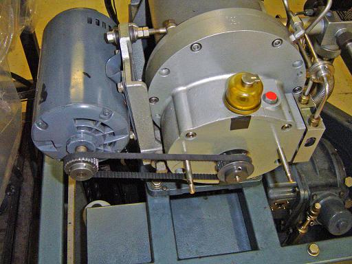 |
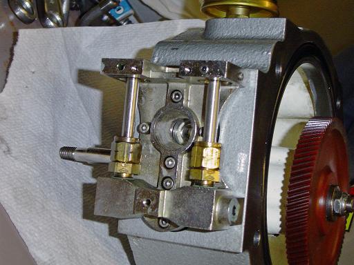
Belt drive (8/25/2007) Turbo pump gear box is connected to the drive motor with a belt. The drive shaft is oil sealed and the oil cup is visible directly above the shaft. |
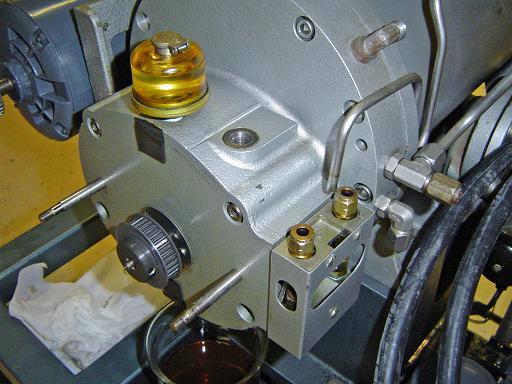 |
Oil fitting (8/25/2007) For models with oil lubricated bearings, oil fittings on the side of the gearbox connect to tubes running to both end caps of the turbo pump. |
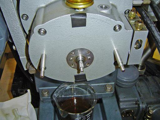 |
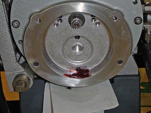
Pulley removed (8/25/2007) Drive pulley is removed showing the magnetic oil seal to the drive shaft. Oil is drained from the gearbox into a beaker. |
 |
Gearbox removed (8/25/2007) Gearbox is removed from turbo pump. |
 |
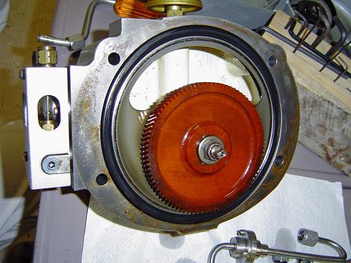
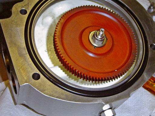
Gearbox end cap (8/25/2007) Gearbox end cap showing drive gear for turbo pump rotors |
 |
Gearbox end cap (8/25/2007) Cleaned |
 |
Cleaned gearbox (8/25/2007)
|
 |
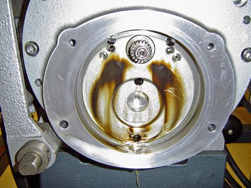
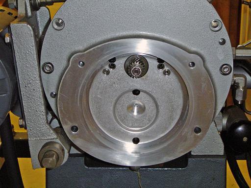
Back end cap (8/25/2007) Cover removed, shown are rotor axial translation nut and bearing locking screws. |
 |
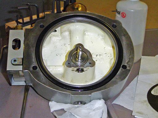
Oil catcher (8/25/2007) Any oil that gets past the bearing drain along the shaft is slung outward into the oil catcher where it is drained into the exhaust of the pump. |
 |
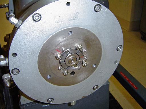
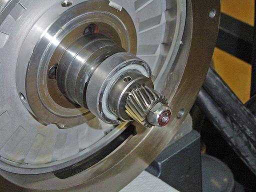
Front bearing (8/25/2007)
|
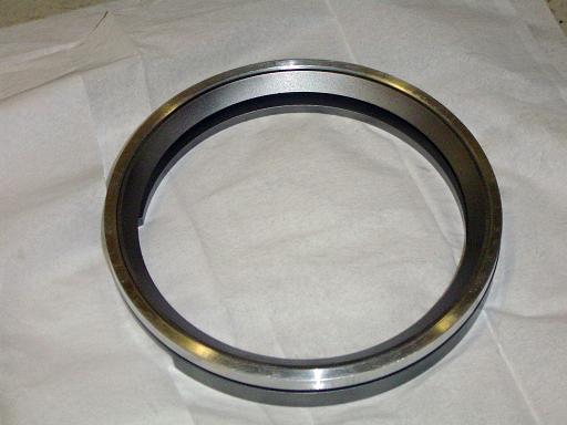 |
Oil catcher (8/25/2007) removed from pump. |
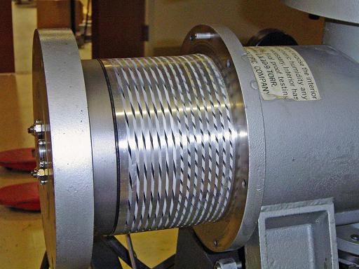 |
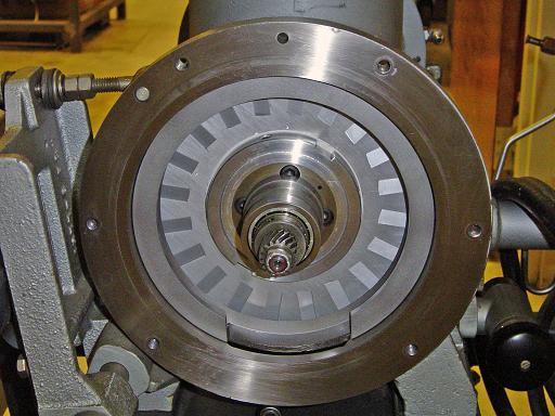
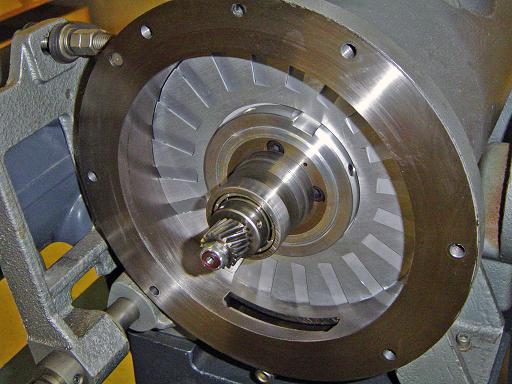
Rotor backing (8/25/2007) Rotor and stator blade assemblies of the pump. |
 |
End plate (8/25/2007) Oil drain / cooling plate attached. |
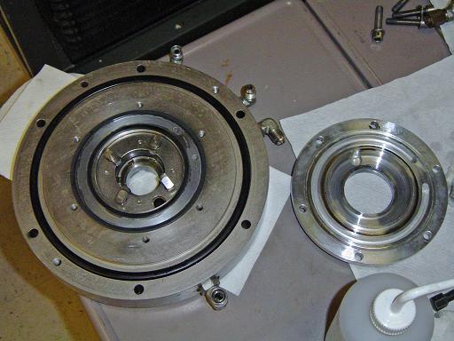 |
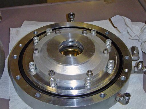
Oil drain plate removed (8/25/2007) Oil drain plate has cooling channels for water to flow through the end cap. Visible in the end plate are the bearing locking screws. |
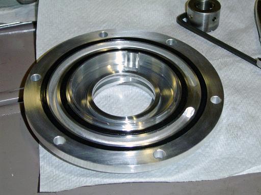 |
Oil drain plate (8/25/2007) Close up of cooling channels. |
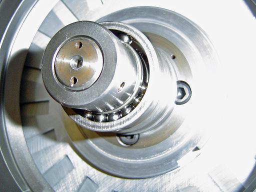 |
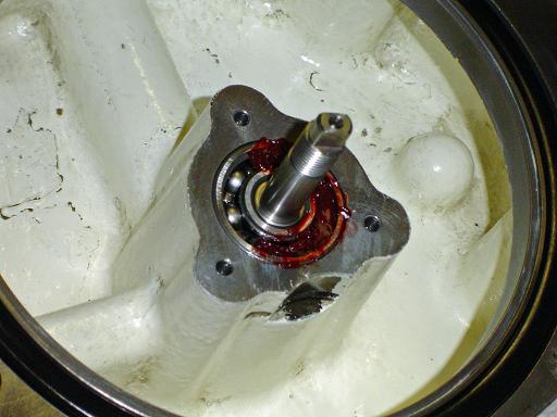
Rear bearing (8/25/2007) Bearing spacer plates had broken off allowing the balls to bunch into one side, causing the shaft to vibrate and the oil slinger assembly to collide with the oil drain plate. |
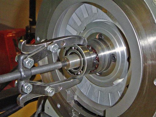 |
Pulling bearing (8/25/2007) Bearings are removed with bearing puller. |
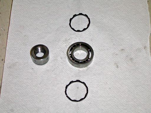 |
Bad bearing (8/25/2007) Bad bearing and broken spacers removed. |
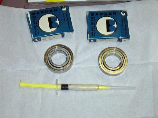 |
New bearings (8/25/2007) New bearings have 5 balls instead of 10 for cooler operation when running with grease. |
 |
Greased bearing (8/25/2007) Greased bearing is installed. |
 |
Gear box bearing (8/25/2007) Gear box bearing is packed with grease. |
 |
Cleaned gear (8/25/2007)
|
 |
Gear box grease (8/25/2007) Grease is packed into the bottom of the gear box so it is transferred to the drive gear when the gearbox is reassembled. |
 |
Oil pump plug (8/25/2007) Outlets to oil pump are plugged. |
 |
Turbo pump (8/25/2007) Reassembled and ready for operation. |
By attempting to reproduce any experiments or devices listed on this domain in part or in whole, you agree to hold me harmless against any lawsuit or liability. Copyright © 1998 - 2005 by Andrew Seltzman. All rights reserved. |
|
| Contact me at: admin@rtftechnologies.org | |