| IEC Fusion Reactor Test Update Page |
 |
 |
 |
 |
 |
 |
 |
Updates:
|
|
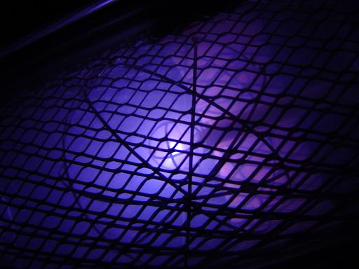 |
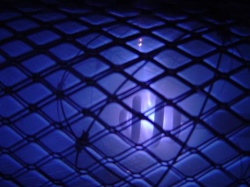
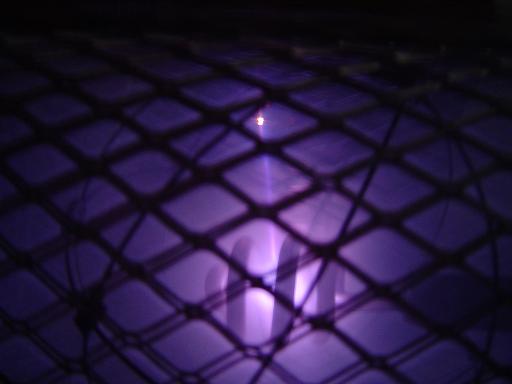
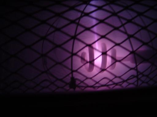
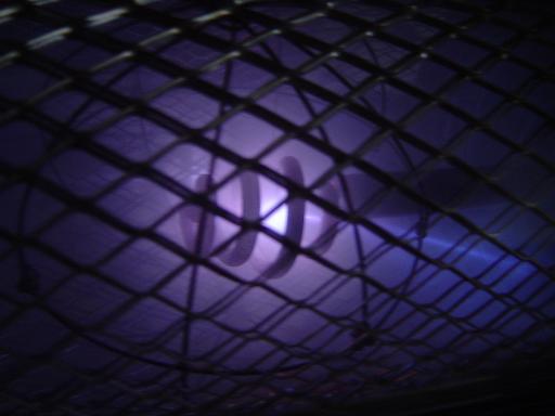
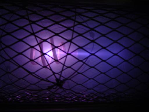
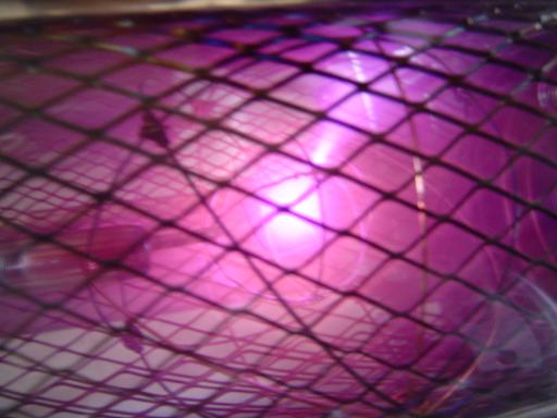
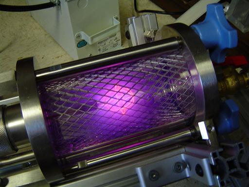
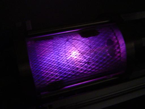
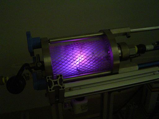
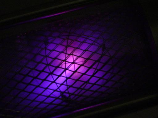
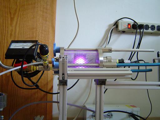
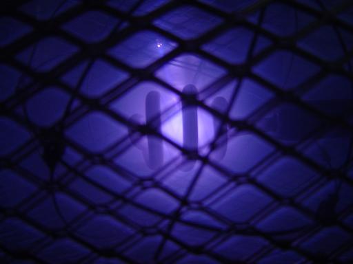
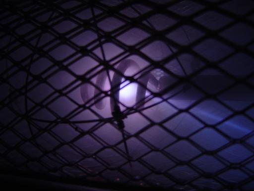
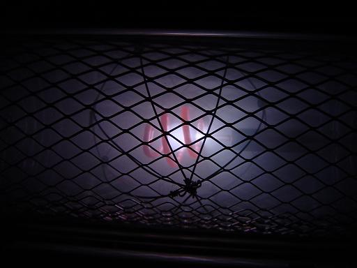
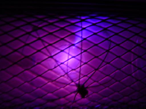
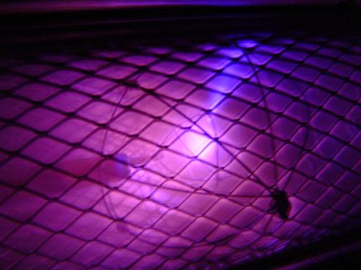
Nitrogen plasma, test 22(11/6/04): Pressure in reactor was maintained at 150 mTorr. Copper 5 ring outer grid was replaced with a spot welded 316 SS 7 ring outer grid. |
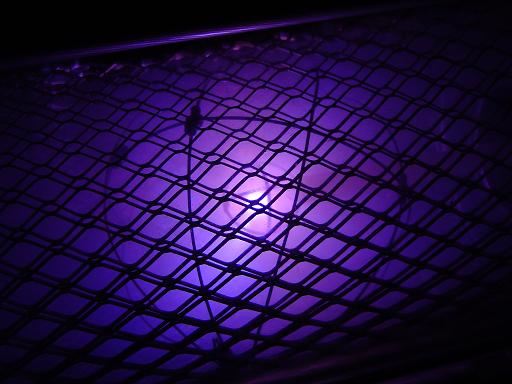 |
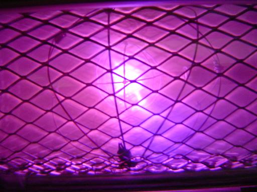
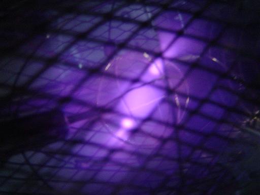
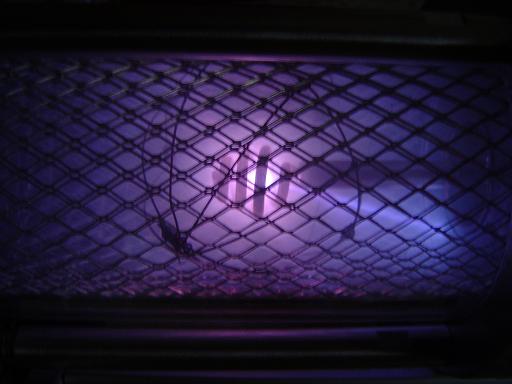
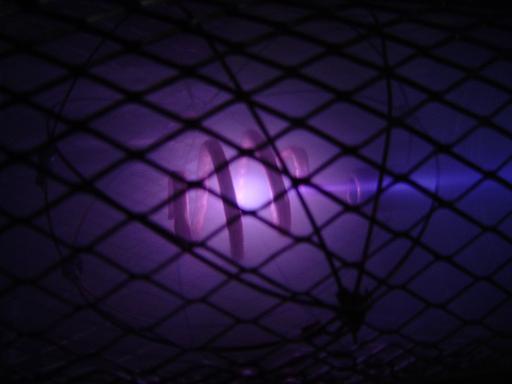
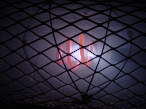
Nitrogen plasma, test 21(11/5/04): Pressure in reactor was maintained at 150 mTorr. Smaller spot welded 316 SS inner grid and better vacuum produced better plasma confinement. |
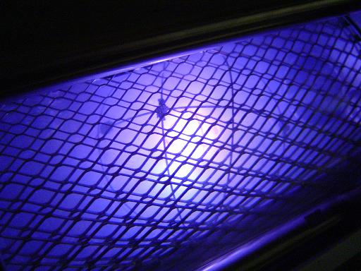 |
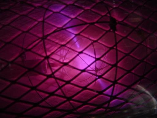
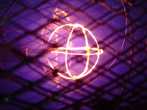
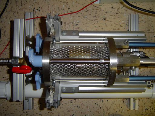
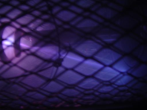
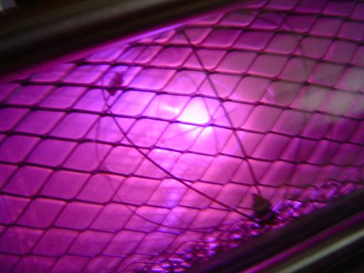
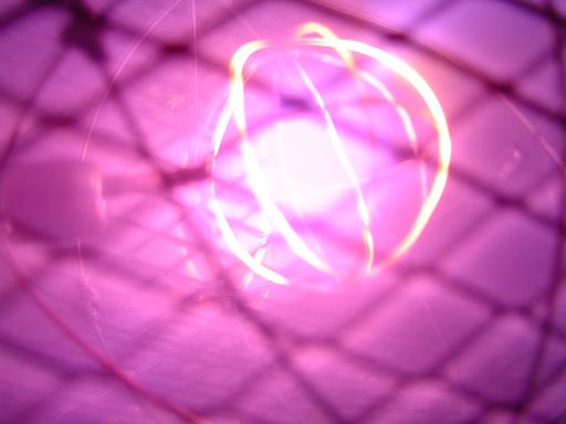
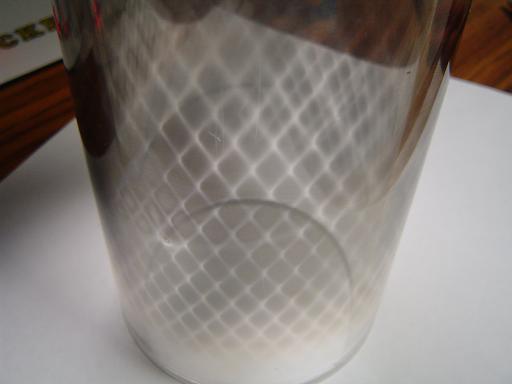
Argon plasma, test 20(9/18/04): Test of gas handling system with Argon. Pressure in reactor was maintained at 250 mTorr. New grid prototyped out of 3 spot welded 316 stainless steel rings.Grid diameter was 0.75". Grid produced a well confined plasma with superior grid transparency. Glass insulator tube has been replaced with a high alumina high temperature ceramic insulator that is no longer damaged by contact with plasma. |
 |
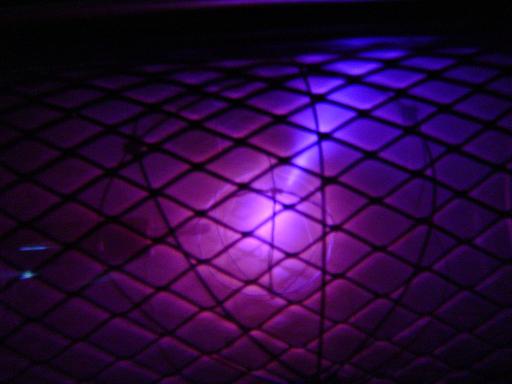
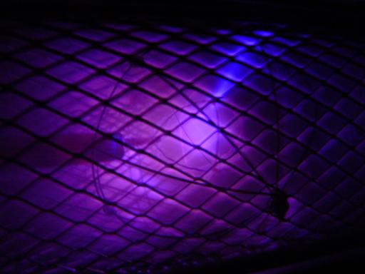
Argon plasma, test 19(8/19/04): Test of gas handling system with Argon at -3kv. Pressure in reactor was maintained at 350 mTorr. Gas handling system is operational but will have to be adapted for lower pressure use. |
 |
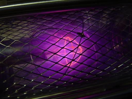
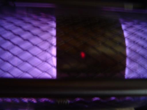
Nitrogen plasma, test 18(7/22/04): Higher value diodes installed. Plasma was initiated at 15 mTorr. Shielding system protected reactor envelope from ion beam. Vacuum was measured at 15 mTorr. As reactor was run pressure climbed to 40 mTorr. Pumping rate will have to be increased with turbo pump. |
 |
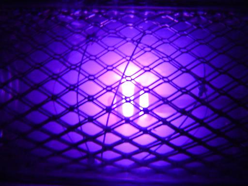
Nitrogen plasma, test 17(7/3/04): Rework of shielding system, internal shield grid increased to three layers. Shield panel is held away from reactor envelope by two layers, greatly decreasing heat conduction. Beam steering magnet strength increased. Vacuum was measured at 15 mTorr. At 15 mTorr current power supply was not able to initiate plasma at -7.5kv. Smaller microwave rectifier diode was burnt out by exceeding maximum inverse voltage while trying to initiate plasma. Pressure was then increased to 30 mTorr, and burnt out diode was disconnected. Photos show plasma generated at 20-30 mTorr at 1/2 wave rectification. Higher value diodes on order. |
|
|
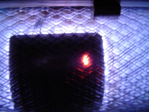
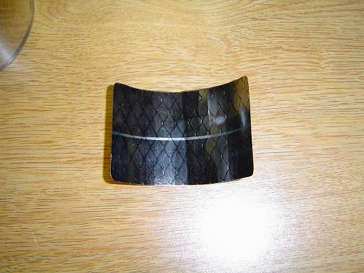
Nitrogen plasma, test 16(6/19/04): Inner grid was brought up to -7.5kv. Solid shield panels and beam steering magnets protected the reactor envelope from being damaged from the ion beam. Plasma containment was greatly improved by greater vacuum. Shield panel prevented ion beam from damaging reactor envelope. At the point of ion collision the shield panel became white hot on the inside and red hot on the outside. Conduction of heat from the shield panel heated the shielding grid and caused minor thermal damage to the reactor envelope Vacuum was measured at 30 mTorr.
|
 |
Nitrogen plasma, test 15(6/19/04): Inner grid was brought up to -7.5kv. A new smaller helical grid was constructed. Plasma confinement was considerably improved. At high potential, multiple plasma beams were seen escaping the grid and a well contained region of plasma was observed at the center. A highly focused ion beam escaped the grid and was aimed at one of the outer grid vertices with a beam steering magnet. As the beam was redirected the ion beam escaped the shielding grid and burned a channel in the reactor envelope. Vacuum was measured at 40 mTorr.
|
 |
Nitrogen plasma, test 14(6/6/04): Inner grid was brought up to -6kv. Extended operation test, reactor walls became warm. Grid was re-aligned, but plasma containment was non ideal. Reactor envelope showed some thermal damage from ion bombardment. Vacuum was measured at 40 mTorr. |
 |
Nitrogen plasma, test 13(6/5/04): Inner grid was brought up to -6kv. A second spiral grid was prototyped. Grid was fabricated out of a nickel-silver brazing rod. Grid mass and high melting temperature permitted extended operation. Vacuum was measured at 40 mTorr. |
|
|
|
 |
Nitrogen plasma, test 12(5/8/04): Inner grid was brought up to -6kv. A spiral grid was prototyped using a copper tube, the increased mass of the copper grid allowed for a longer period at a high voltage potential. Good plasma containment was observed, however the grid melted due to copper's lower melting point. Vacuum was measured at 50 mTorr. |
 |
Nitrogen plasma, test 11(5/8/04): Inner grid was held at -3.5kv. Vacuum levels were increased by ballasting / warming up the pump for one hour. Increased vacuum helped plasma containment by allowing increased voltage on the inner grid. A filter capacitor was added across the hv to the reactor, however this caused problems and was removed. Vacuum was measured at 25-30 mTorr. More vacuum system work and a possible degassing of the plastic will be required. |
 |
Deuterium plasma, test 10(4/7/04): Inner grid was held at -3kv. Deuterium supply was tested, heavy water was electrolyzed and deuterium was injected into the reactor. No beta, gamma, or x-ray radiation was detected at the surface of the reactor envelope. Based on plasma temperature it is extremely unlikely that any D + D => He3 + N fusion reactions took place. Vacuum was measured at 35 mTorr. Higher inner grip power will not be effective in increasing plasma containment and temperature to fusion levels until better vacuum(about 10 mTorr) can be obtained. |
 |
Nitrogen plasma, test 9(4/3/04): Inner grid was held at -3kv. Several narrow ion / electron beams are visible escaping the inner grid. Vacuum was measured at 35 mTorr. Vacuum system was leak tested by applying ethanol to the intersections of components. No leaks were found. When the reactor is isolated from the pump, the pump will reach 15 mTorr, however with the chamber valve open and all interior components removed it will only reach 30 mTorr. The plastic walls of the chamber are probably outgassing, causing this problem. An electrolysis assembly has been constructed for supplying deuterium from heavy water. Heavy water is on order. |
 |
Nitrogen plasma, test 8(3/29/04): Inner grid was held at -3kv, and -6kv. The beginning of a diffuse ion / electron beam was visible escaping the inner grid. The beam alternated between several areas of the grid. Inner grid was re-aligned and re-centered. Teflon pipe paste was applied to the interface between the flare fitting and the steel vacuum hose. Vacuum was measured at 40 mTorr. |
 |
Nitrogen plasma, test 7(3/27/04): Inner grid was held at -2kv, -3kv, and -6kv. Grid became red near the bugle jet. Outer grid was modified to include two more rings to improve plasma focus. Focus improved and plasma containment at higher grid voltages is now possible. Vacuum was measured at 70 mTorr. Picture shown is -3kv run, also see: |
 |
Nitrogen plasma, test 6(3/25/04): Inner grid was held at -1.5kv. Grid remained cool. Inner grid was re-aligned, only one bugle jet was observed. Vacuum was measured at 90 mTorr. Deposition in the chamber walls is still present. |
 |
Nitrogen plasma, test 5(3/24/04): Inner grid was held at -1.5kv. Grid remained cool and plasma containment was observed. This test used the modified inner grid with 5 containment rings instead of 3. At a lower input voltage then previous tests(about -1.5kv) plasma containment in the center was observed along with two bugle jets. Vacuum was not measured but is estimated to be about 200 mTorr. Outer grid may still be modified to include more rings to improve plasma focus. |
 |
Nitrogen plasma, test 4(3/23/04): Inner grid was held at -6kv. Grid became a white hot. Vacuum was not measured but is estimated to be about 200 mTorr. At low power(grid not glowing) contained plasma and a bugle jet was observed, however at higher powers this effect dies out. Outer and inner grids may be modified to include more rings to improve plasma focus. New glass insulation rod still showed some signs of metal deposition and minor damage at the tip. Some sort of shield for the rod may be necessary. Deposition on the walls of the chamber occurs with each run but is easily cleaned. |
 |
Nitrogen plasma, test 3(3/21/04): Inner grid was held at -6kv. Grid became a brilliant white. Vacuum was not measured but is estimated to be about 200 mTorr. Half wave rectification of both sides of a neon sign transformer was used to provide -6kv at a higher current than before. Platinum/copper deposited made the glass tube conductive toward the end of the test. Plasma was observed in contact with the tube. The tip of the tube then started throwing off sparks and became red hot. Reactor was then shut down, dismantled and cleaned. No damage occurred to any part other then the glass tube. The tube was replaced with one that narrows toward the tip to provide better insulation. The tube now terminates slightly farther from the inner grid to decrease metal deposition and prevent contact with plasma. |
 |
Nitrogen plasma, test 2(3/19/04): Inner grid was held at -6kv. Grid became orange. Vacuum was not measured but is estimated to be about 200 mTorr. Outer grid was installed. Previously a small piece of paper towel held the glass insulating rod in position with the inner grid standoff. The paper towel began to blacken and deposit carbon on the chamber walls. The paper towel was removed and the chamber walls were cleaned with a light abrasive(car polish). It was then observed that an extremely fine coat of platinum/copper was being deposited on the outer grid, chamber walls, and glass insulator. There is no obvious damage to the inner grid, however this might cause problems in the future. Plasma was observed traveling from the inner grid to the inside of the class tube.
|
 |
Nitrogen plasma, test 1(3/17/04): Inner grid was held at -6kv. Grid became red hot in places. Vacuum was not measured but is estimated to be about 200 mTorr(microns). Star mode was not achieved due to the lack of a geodesic outer grid and the low vacuum level during the test. Half wave rectification of one side of a 12kv center tapped neon sign transformer was used to provide -6kv.
|
| Useful links: http://www.fusor.net/ Open Source Fusion Research Consortium. |
|
By attempting to reproduce any experiments or devices listed on this domain in part or in whole, you agree to hold me harmless against any lawsuit or liability. Copyright © 1998 - 2005 by Andrew Seltzman. All rights reserved. |
|
| Contact me at: admin@rtftechnologies.org | |
