| Mark 2 Ion Hemisphere |
 |
 |
 |
 |
 |
 |
 |
| Overview:
|
|
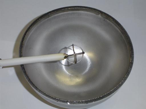 |
Hemisphere: 4" diameter hemisphere with 0.75" diameter inner grid. New reactor will present more optimal 1:5 grid ratio. |
 |
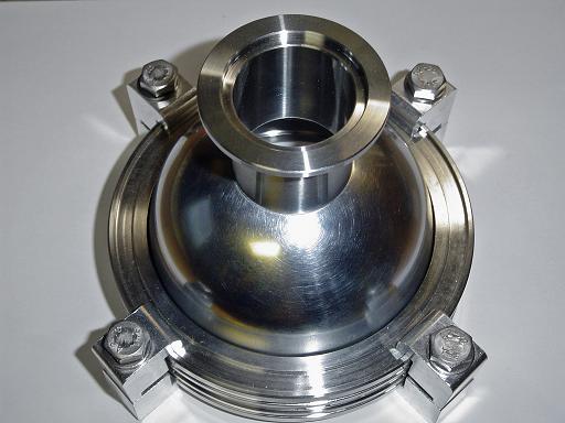
ISO-100 Flange: 4" hemisphere will be machined to fit five 2.75" CF half nipples and welded to ISO flange. O-ring will seal both hemispheres together. |
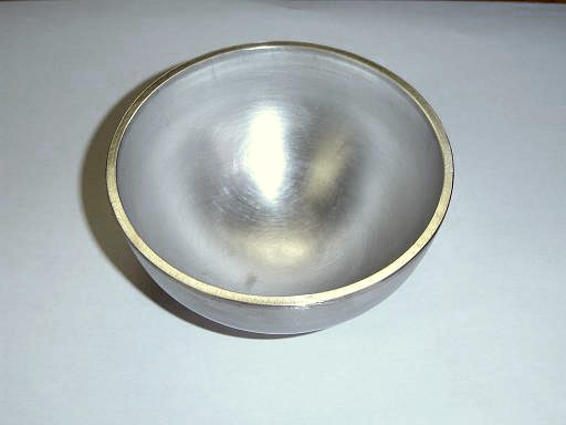 |
Hemisphere: Hemisphere face sanded down to present even face to fit flange. |
 |
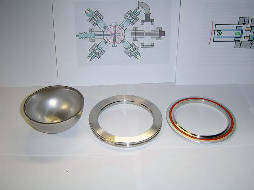
Components: Each half of the reactor core will consist of 1 NW40 weld stub, one ISO-100 flange, and a 4" diameter hemisphere. |
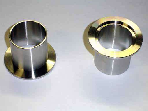 |
NW-40 Weld Stub: NW40 weld stubs will be used to connect the reactor core to the high voltage feedthrough and vacuum hub. |
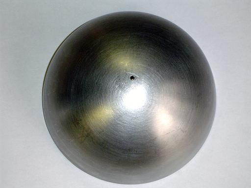 |
Index Hole: An index hole is drilled on the hemispheres axis as a reference point for machining. |
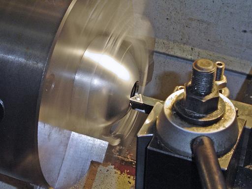 |
Primary Bore(1/18/2005): A small hole is bored out with the lathe in order to fit in a boring bar that will turn the hole out to the proper size. |
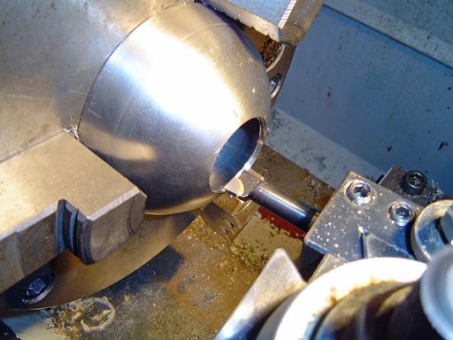 |
Secondary Bore(1/19/2005): A 1.5" OD hole is bored out with the lathe using a boring bar in order to fit the vacuum flange. The hole is counter bored to provide a lip for the flange to sit on. |
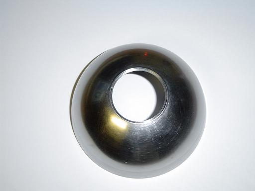 |
Counter Bored Hole(1/19/2005):
|
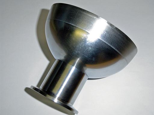 |
Flange Fit(1/19/2005): Flange firs tightly into bored hole. |
 |
Hemisphere (1/19/2005): Hemisphere 1 assembled and ready for welding. |
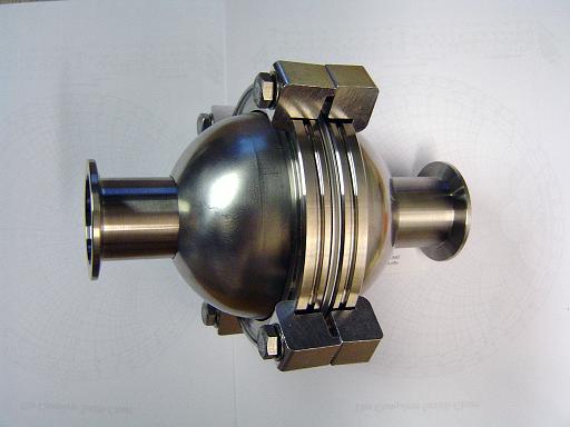 |
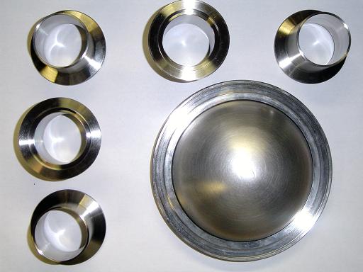
Core Components (2/1/2005): Core machining complete and ready for welding. |
| Useful links: http://www.fusor.net/ Open Source Fusion Research Consortium. |
|
By attempting to reproduce any experiments or devices listed on this domain in part or in whole, you agree to hold me harmless against any lawsuit or liability. Copyright © 1998 - 2005 by Andrew Seltzman. All rights reserved. |
|
| Contact me at: admin@rtftechnologies.org | |