| Mark 3 Anode Layer Ion Source |
 |
 |
 |
 |
 |
 |
 |
| Overview: An anode layer ion source consists of a positively biased ring shaped anode between two grounded magnetic poles that create a radial magnetic field across the anode ring. Electrons drift above the ring due to the ExB force and ionize gas (either ambient or a controlled flow over the anode ring) which is then directed into a rind shaped beam. Anode layer sources have been used as satellite thrusters, plasma sources, for thin film deposition or surface treatment.
|
|
Ion Source Specs:
|
|
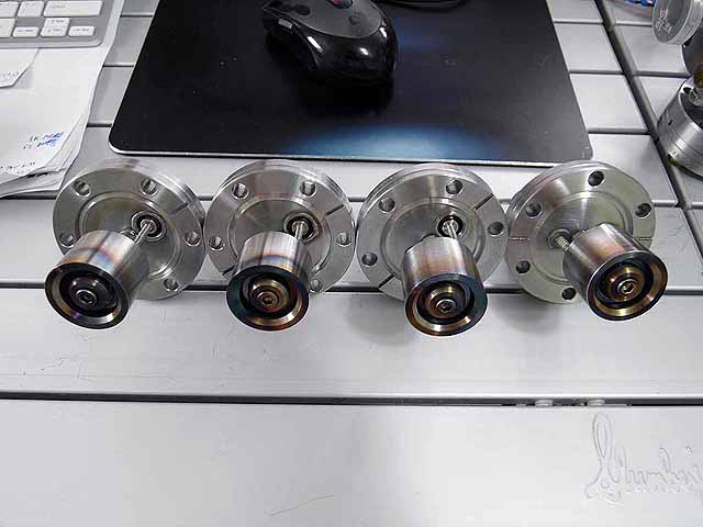 |
Complete Ion Sources
|
 |
Complete Ion Source
|
 |
Complete Ion Source
|
 |
Quad Ion Source Fusor Four ion sources mounted on fusor |
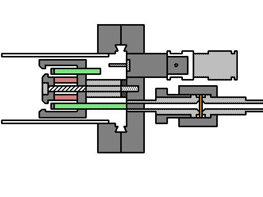 |
Ion Source CAD (3/14/2009) CAD of anode layer ion source. |
 |
Ion Source CAD (3/14/2009) CAD of anode layer ion source casing. |
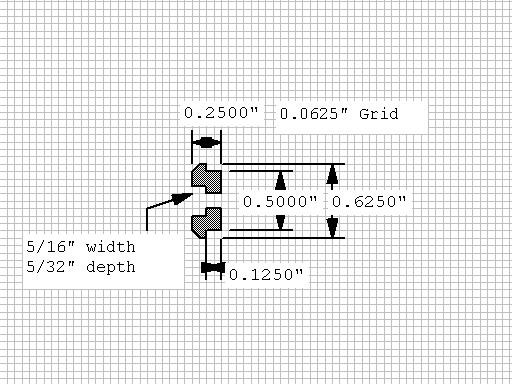 |
Ion Source CAD (3/14/2009) CAD of anode layer ion source pole peace. |
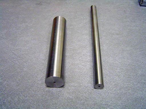 |
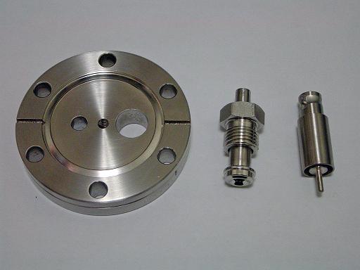
410 SS Bar stock (3/14/2009) 410 stainless steel is a magnetic alloy allowing it to concentrate the magnetic field at the gap between the pole pieces while retaining the chemical resistant properties of stainless steel. 1.25" bar stock is used for the ion source casings (Mcmaster 86705K141) 0.625" bar stock is used for the ion source central pole piece. (Mcmaster 86705K421) |
Casing Blanks (3/14/2009) 1" long blanks for the ion source casings. |
|
 |
Casing Construction (3/14/2009) Facing off the casing and turning down to 1" length after cutting off blank with band saw. |
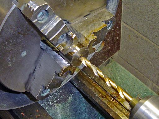 |
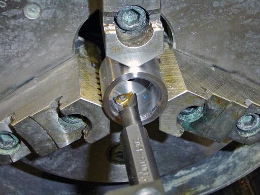
Casing Construction (3/14/2009) Drilling out center of casing. |
 |
Casing Construction (3/14/2009) Increasing drill size. |
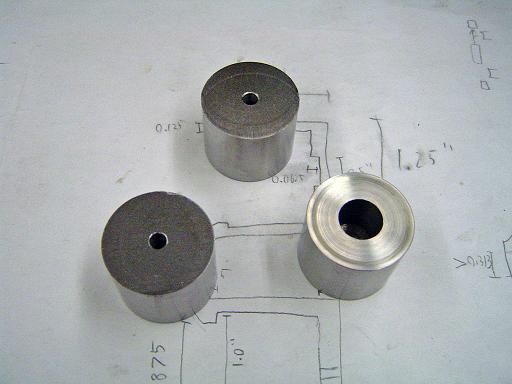 |
Casing Construction (3/14/2009) Casing that has been faced off and drilled with those just cut off with the band saw. |
 |
Casing Construction (3/14/2009) Drilled out to almost 0.875" ID |
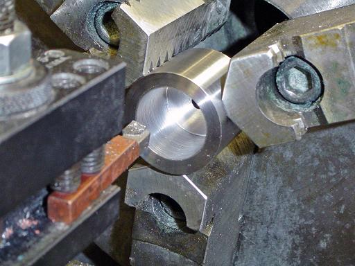 |
Casing Construction (3/14/2009) Carbide tool is used to take ID out to 0.875" and to flatten out bottom of casing. |
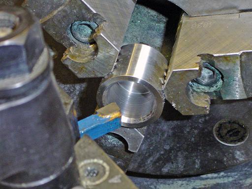 |
Casing Construction (3/14/2009) Pole piece angle turned into face. |
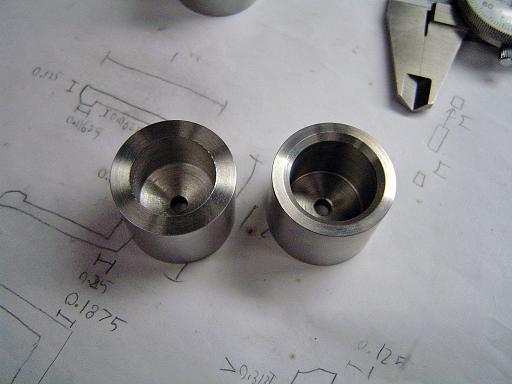 |
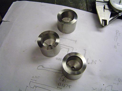
Casing Construction (3/14/2009) Casing that has been bored out to 0.875", angled, and flattened on the bottom next to one that has just been drilled. |
 |
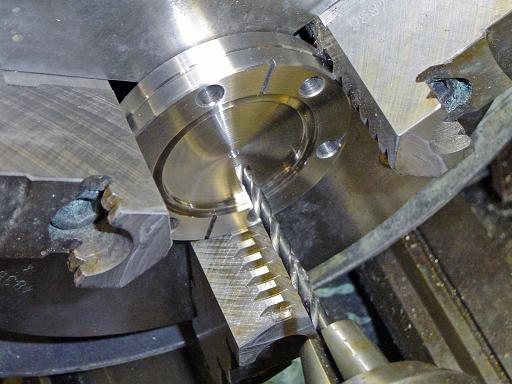
Casing Construction (3/14/2009) Boring bar is used to turn out inner relief to 1" and form back end of pole piece lip. |
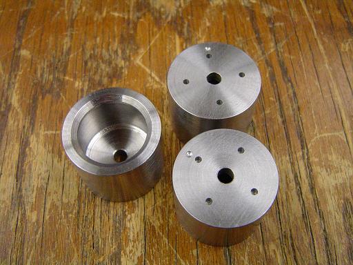 |
Casing Construction (3/14/2009) After turning on the lathe is complete, four pilot holes at 0.75" radius are center drilled on the mill. |
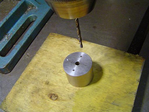 |
Casing Construction (3/14/2009) Feed through holes for 0.125" OD high alumina ceramic tubing are drilled on a drill press. |
 |
Magnet Installation (3/14/2009) N40 rare earth magnet provides magnetic field. Magnet specs:
|
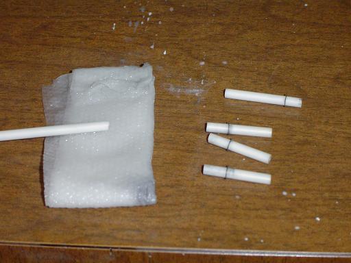 |
Alumina Standoffs (3/14/2009) Alumina standoffs are cut using diamond power coated cutter disk. (Mcmaster 8746K11) Shaft retaining snap rings position the standoffs along their length. (Mcmaster 97633A110) |
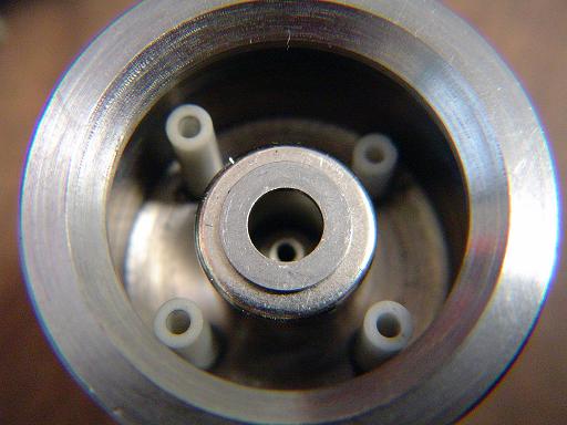 |
Alumina Standoffs (3/14/2009) Alumina standoffs are installed through feed through holes. Spacer washer in place. (Mcmaster 90945A740) |
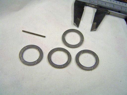 |
Anode Construction (3/14/2009) Anodes are fabricated out of SS shims, 0.875"OD 0.626"ID. (Mcmaster 94773A778) Shims are scribed at 0.75" radius.
|
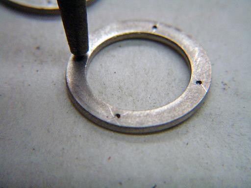 |
Anode Construction (3/14/2009) Hole locations are punched into surface. |
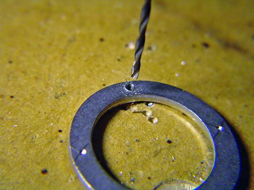 |
Anode Construction (3/14/2009) Holes are drilled to allow welding of threaded rods into anode. |
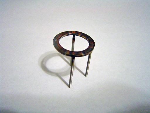 |
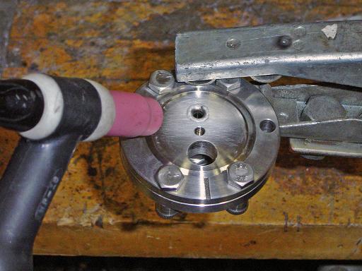
Anode Construction (3/14/2009) 1" long 0-80 threaded rods are TIG welded into anode (Mcmaster 95412A300) |
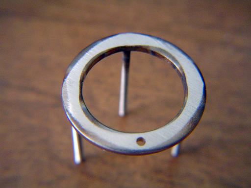 |
Anode Construction (3/14/2009) Surface is belt sanded flat to provide uniform electric field |
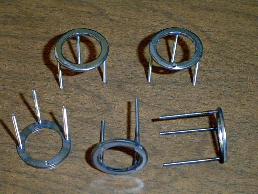 |
Anode Construction (3/14/2009) Five anodes for set of injectors. |
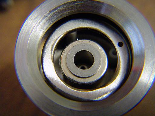 |
Anode Installation (3/14/2009) Anodes are installed into ion sources with threaded rods sliding through center of alumina standoffs. |
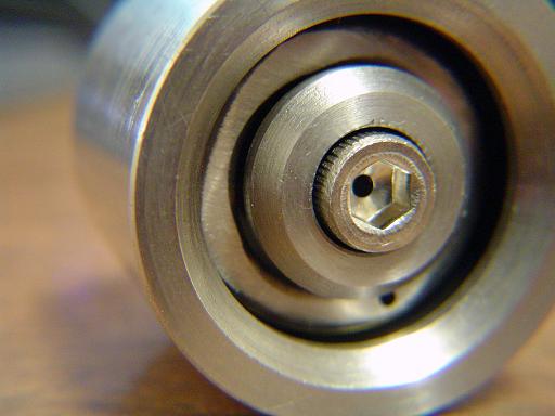 |
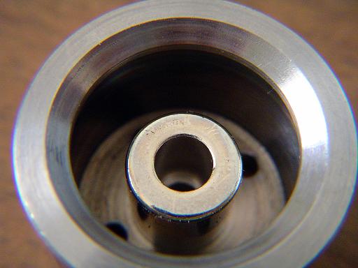
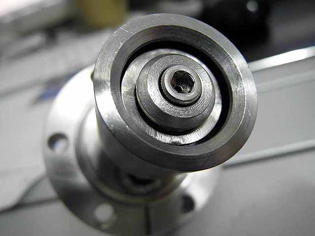
Center Pole Piece (3/14/2009) Center pole piece is installed with 10-32 screw traveling through injector body. (Mcmaster 93235A248) |
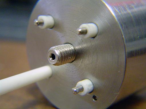 |
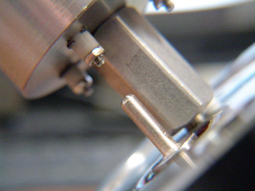
Anode Feedthroughs (3/14/2009) Threaded rod ends on other side of standoffs. |
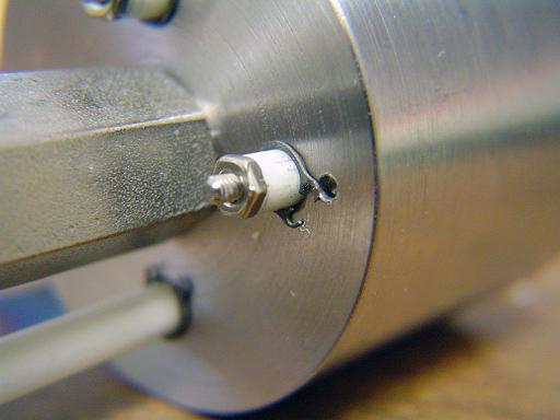 |
Anode Feedthroughs (3/14/2009) Snap rings (Mcmaster ) and nuts installed on other sides of standoffs. (Mcmaster 91841A115) |
|
|
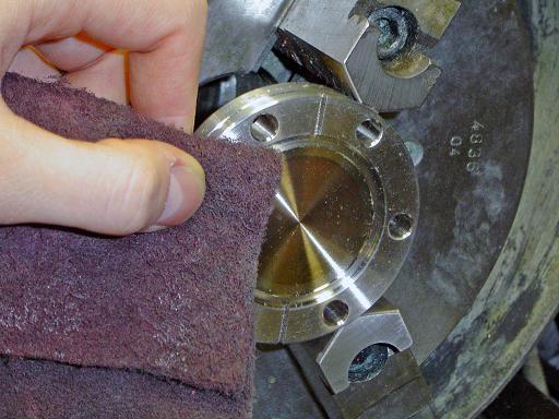 |
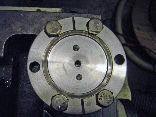
Flange Construction (3/14/2009) Blank 2.75" conflat flange is cleaned with scotchbrite. |
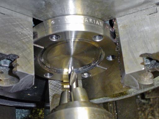 |
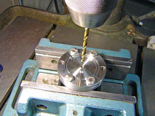
Flange Construction (3/14/2009) Flange is center drilled at the center. |
 |
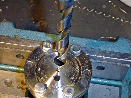
Flange Construction (3/14/2009) Hole is drilled to 0.3125" depth in center of flange. |
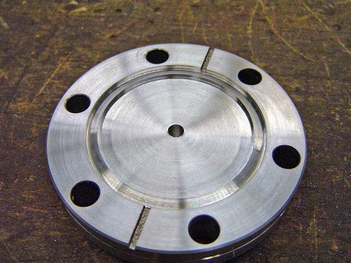 |
Flange Construction (3/14/2009) Drilled flange ready for taping. |
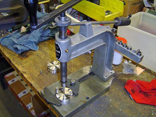 |
Flange Construction (3/14/2009) Flange is tapped with 10-32 tap. |
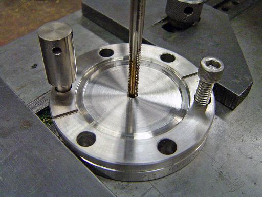 |
Flange Construction (3/14/2009) Flange is tapped with 10-32 tap. |
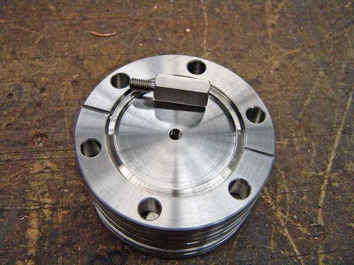 |
Flange Construction (3/14/2009) Taped flange. |
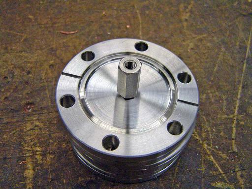 |
Flange Construction (3/14/2009) Vented standoff screws into flange. (Mcmaster 91075A174) |
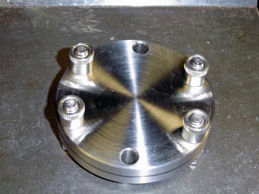 |
Flange Construction (3/14/2009) Round nuts are used to allow flange to be evenly clamped in a vice. |
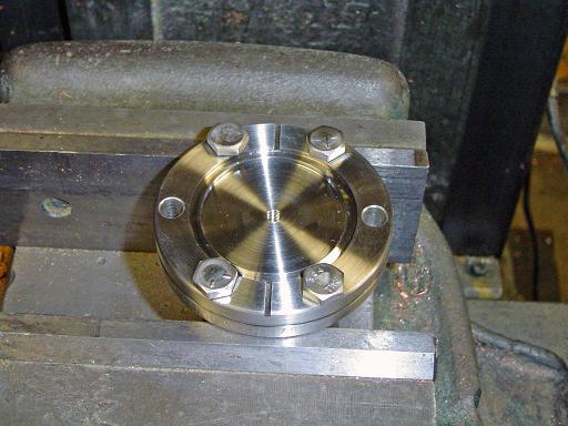 |
Flange Construction (3/14/2009) Flange clamped in mill vice. |
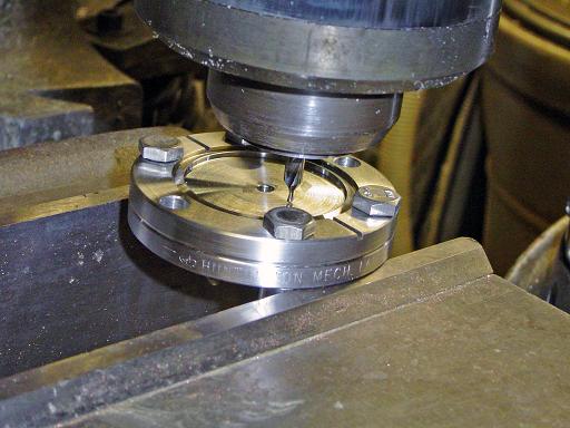 |
Flange Construction (3/14/2009) Pilot holes for Feedthroughs are center drilled into flange. |
 |
Flange Construction (3/14/2009) Center drilled flange. |
 |
Flange Construction (3/14/2009) Holes are drilled out to size. |
 |
Flange Construction (3/14/2009) 0.25" hole is drilled for gas feed through and 0.5" hole is drilled for MHV feed through. 0.25 hole is 0.375" from center, 0.5" hole is 0.4375" from center 10-32 thread is drilled to 0.3125" depth in center of flange. |
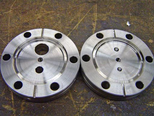 |
Flange Construction (3/14/2009) Flanges before and after drilling to size. |
 |
Flange Construction (3/14/2009) Flange with 1/4" VCR gas feed through and MHV electrical feed through. |
 |
Flange Construction (3/14/2009) Feedthroughs TIG welded to flange |
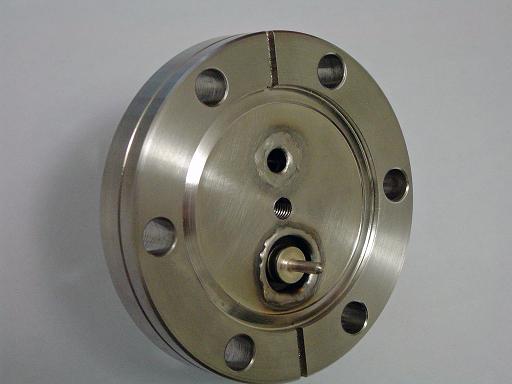 |
Flange Construction (3/14/2009) Completed flange. |
|
|
 |
Ion Source Assembly (3/14/2009) Source screws into flange. |
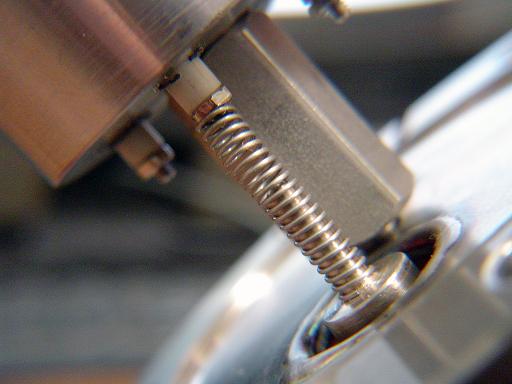 |
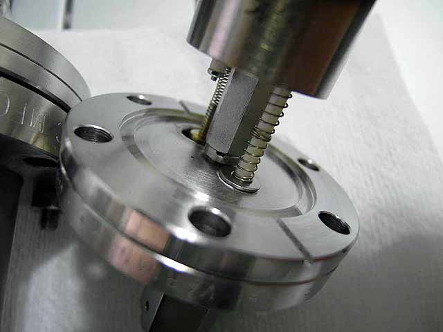
Ion Source Assembly (3/14/2009) Spring connects electrical feed through to anode nut. (Mcmaster 9663K12) |
 |
Ion Source Assembly (3/14/2009) Alumina tube allows source body to be filled with feed gas. |
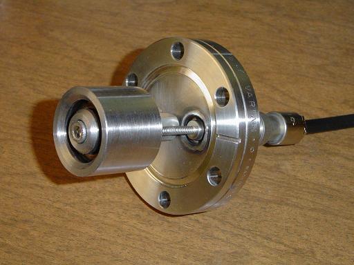 |
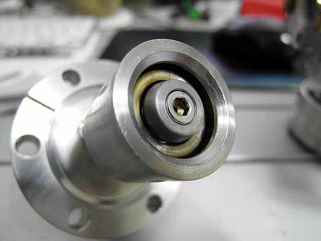
Ion Source Complete (3/14/2009) Completed ion source. |
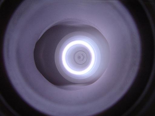 |
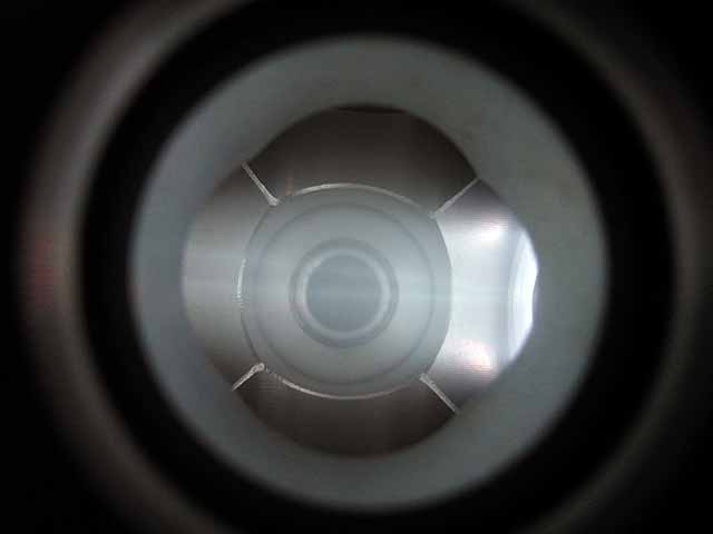
Ion Source Operation (3/14/2009) Front view. |
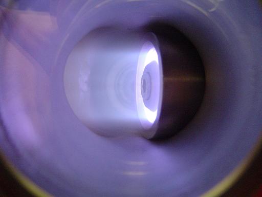 |
Ion Source Operation (3/14/2009) Side view. |
 |
Ion Source Operation (3/14/2009) Side view with faraday cup collector. |
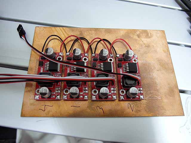 |
Ion Source Power Supply (7/30/2014) Buck converters for high voltage power supply control. |
 |
Ion Source Power Supply (7/30/2014) Emco F40 high voltage power supplies, 0-12v input voltage 0-4kV output voltage. |
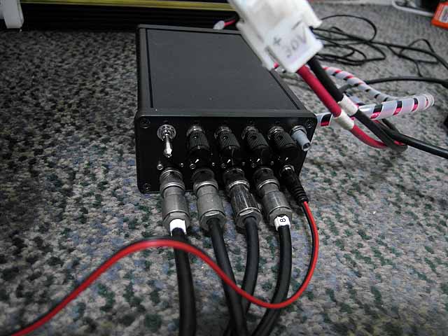 |
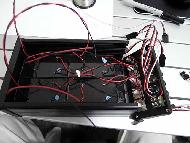
Ion Source Power Supply (7/30/2014) Complete power supply |
 |
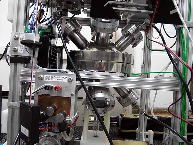
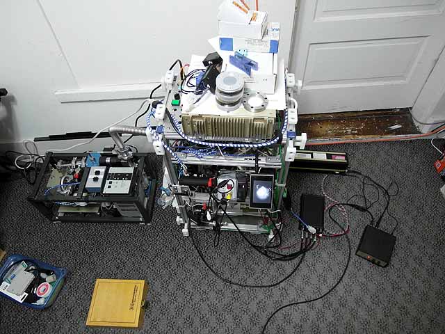
Ion Source Operation (7/30/2014) Ion Source operation in test bed |
 |
Ion Source Operation (7/30/2014) Ion Source operation in test bed |
 |
Fusor Setup (7/30/2014) With 4 ion sources |
|
Fusor Setup (7/30/2014) With 4 ion sources |
 |
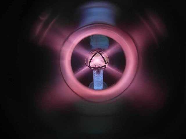
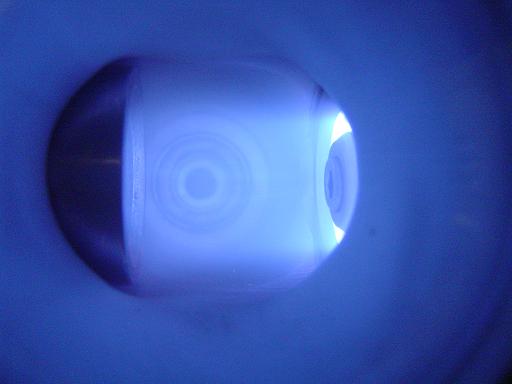
Fusor plasma (7/30/2014) With 4 ion sources, argon plasma |
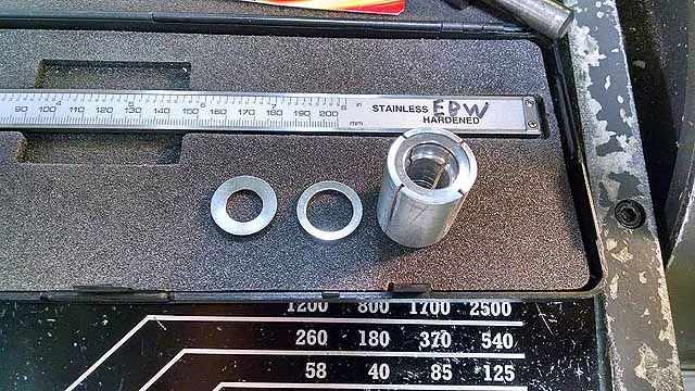 |
Focusing Anode Ring (3/06/2016) Stainless Steel Belleville Disc Spring (mcmaster 9713K437) (6.6 degree inward angle) and jig to bore to correct ID |
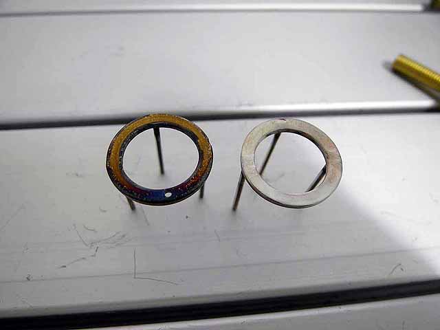 |
Focusing Anode Ring (3/06/2016) Beveled anode ring with original flat ring |
 |
SmCo Magnet (3/06/2016) SmCo magnet is compatible with deuterium and tolerant of high temperatures for long operation runs (up to 300C instead of 80C for the NdFeB) |
 |
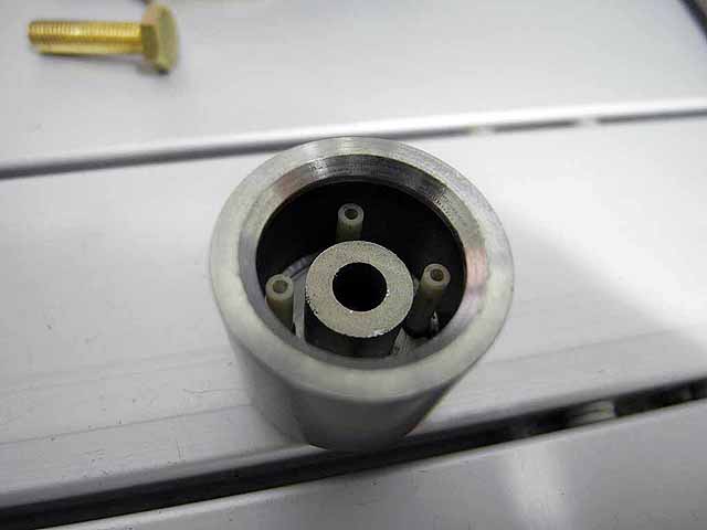
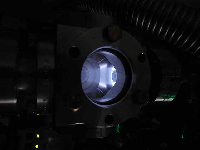
Focusing Anode Ring (3/06/2016) Installed in ion source |
 |
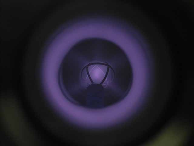
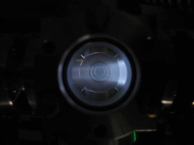
Focusing Anode Ring (3/06/2016) Ion beam with focusing anode ring |
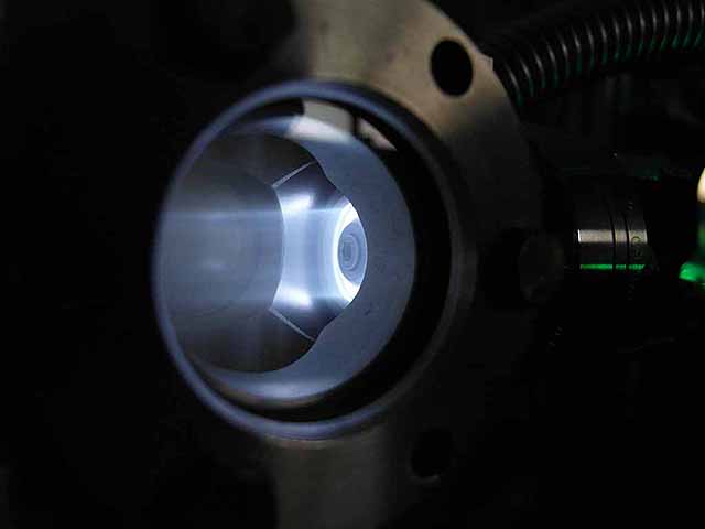 |
Focusing Anode Ring (3/06/2016) Ion beam with focusing anode ring |
Focusing Anode Ring (3/06/2016) Ion beam with focusing anode ring |
|
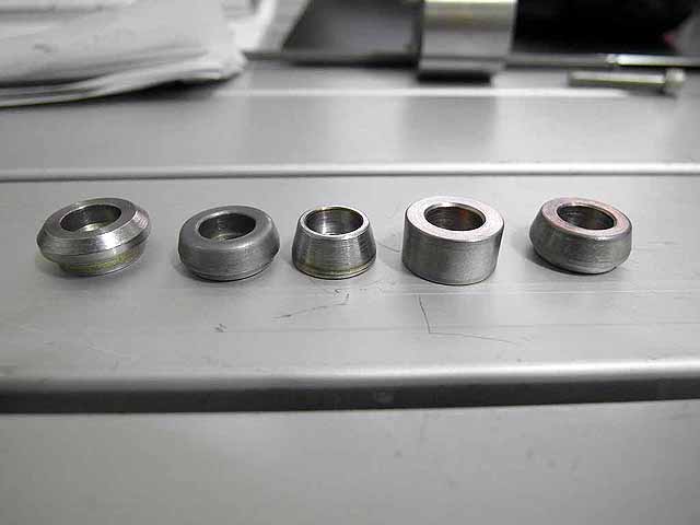 |
Pole Piece Testing (3/06/2016)
|
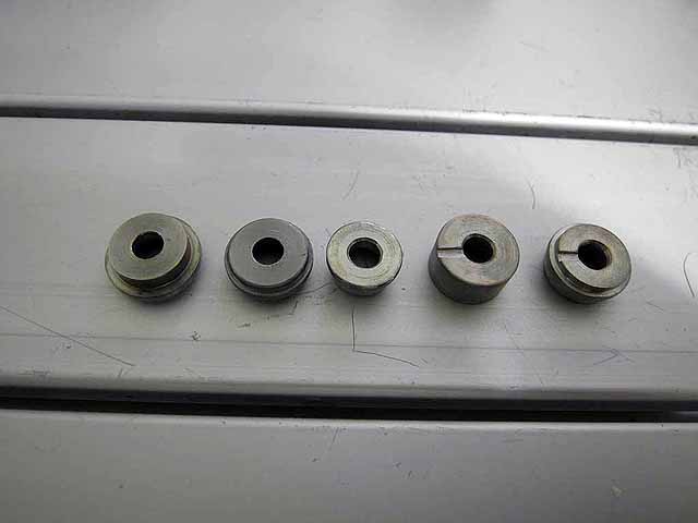 |
Pole Piece Testing (3/06/2016) Version 4 and 5 have a pump out groove milled in the base to vent the trapped volume inside the magnet |
 |
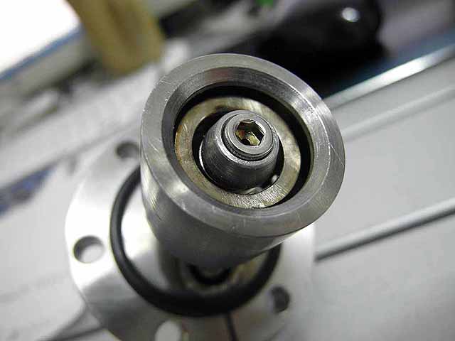
Pole Piece Testing (3/06/2016) Version 2 |
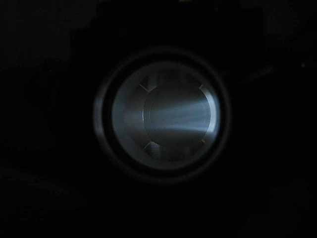 |
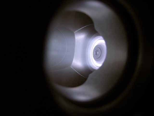
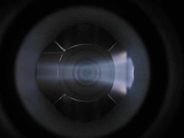
Pole Piece Testing (3/06/2016) Version 2 plasma focus |
 |
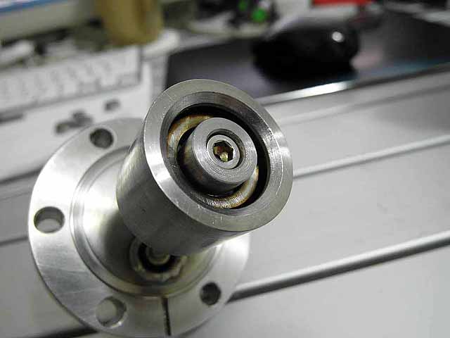
Pole Piece Testing (3/06/2016) Version 2, recessed |
 |
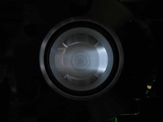
Pole Piece Testing (3/06/2016) Version 2, recessed plasma focus |
 |
Pole Piece Testing (3/06/2016) Version 3, recessed |
 |
Pole Piece Testing (3/06/2016) Version 3, recessed plasma focus |
 |
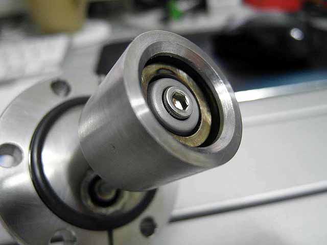
Pole Piece Testing (3/06/2016) Version 3 |
 |
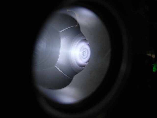
Pole Piece Testing (3/06/2016) Version 3 plasma focus |
 |
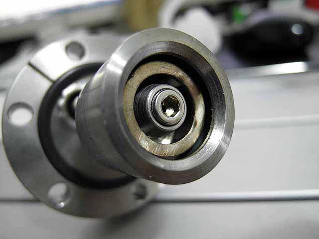
Pole Piece Testing (3/06/2016) Version 4 |
 |
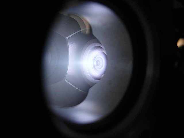
Pole Piece Testing (3/06/2016) Version 4 plasma focus |
|
Pole Piece Testing (3/06/2016) Version 5 |
 |
Pole Piece Testing (3/06/2016) Version 5 plasma focus |
 |
Pole Piece Testing (3/06/2016) Version 5 plasma focus |
 |
Pole Piece Testing (3/06/2016) Pump out duct in standoff washer. Standoff has axially drilled pump out hole, pump out duct in washer prevents trapped volume in washer interior. Standoff washer designed to prevent hex standoff from sitting on the weld of the MHV feed through which was causing a slight misalignment of the ion source. |
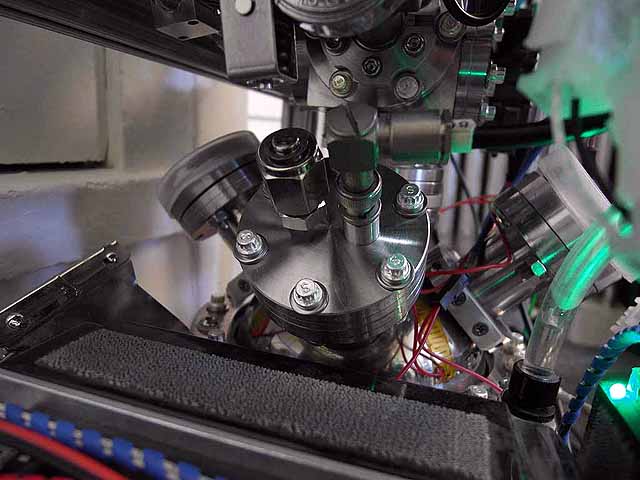 |
Pole Piece Testing (3/06/2016) Modified sources installed, now using copper o-rings instead of viton |
|
Fusor plasma (3/06/2016) With 4 ion sources, deuterium plasma |
|
|
| Useful links: http://www.fusor.net/ Open Source Fusion Research Consortium. |
|
By attempting to reproduce any experiments or devices listed on this domain in part or in whole, you agree to hold me harmless against any lawsuit or liability. Copyright © 1998 - 2005 by Andrew Seltzman. All rights reserved. |
|
| Contact me at: admin@rtftechnologies.org | |