| Mark 3 ECRF Driver |
 |
 |
 |
 |
 |
 |
 |
| Overview: Driver system to supply RF power to the ion injectors in order to excite electrons at their ECRF frequency. |
|
|
|
|
|
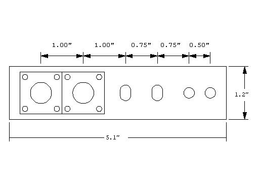 |
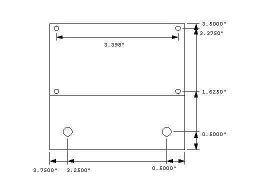
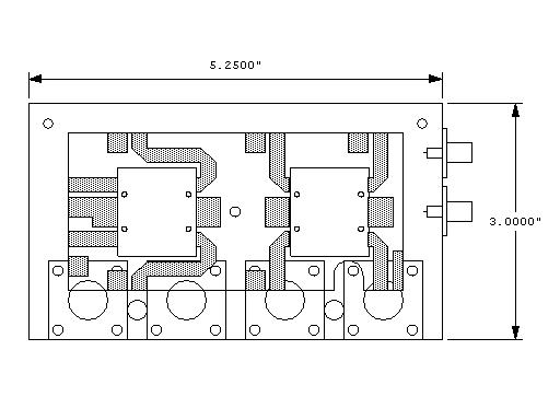
RF input panel CAD (5/25/2007) RF panel CAD |
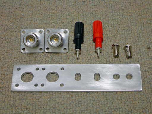 |
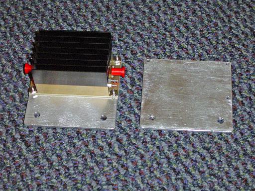
RF amplifier input panel (5/25/2007) Aluminum panel is milled to mount RF input, output and power connectors. |
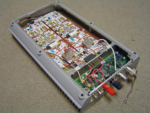 |
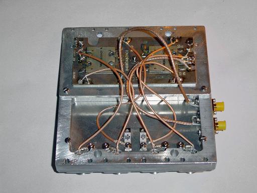
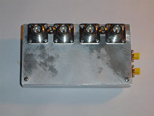
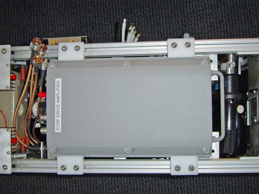
ECRF drive amplifier (5/25/2007) Connector panel is mounted on amplifier replacing original panel. |
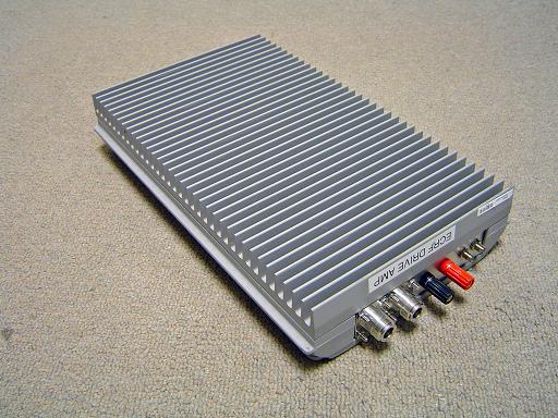 |
ECRF drive amplifier (5/25/2007) Modified amplifier. |
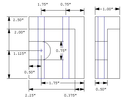 |
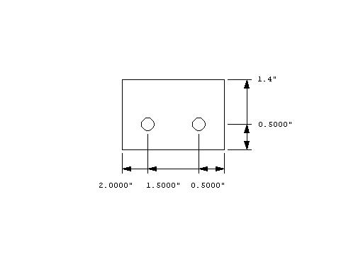
Amplifier mounting block CAD (5/25/2007) Cad of mounting block to attach amplifier to frame. |
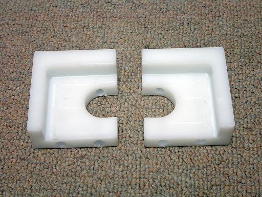 |
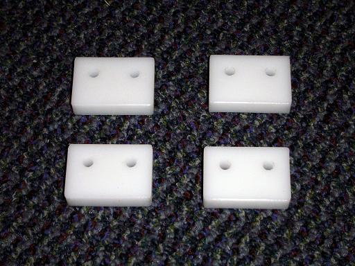
Amplifier mounting blocks (5/25/2007) HDPE blocks attach amplifier to frame. |
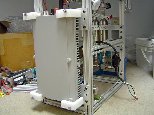 |
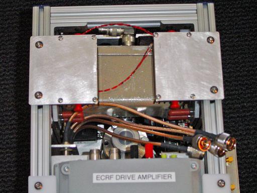
ECRF amplifier mounted (5/25/2007) Amplifier mounts to reactor frame. |
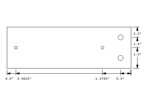 |
Power supply mounting plate CAD (5/25/2007) Cad of mounting plate to attach power supply to frame. |
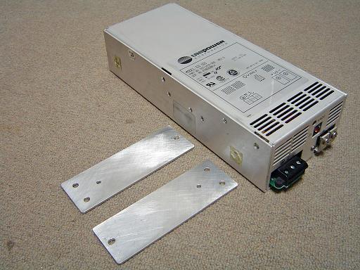 |
ECRF amplifier power supply (5/25/2007) 26V at 25A power supply will power ECRF amplifier and grid cooling loop heat exchanger. |
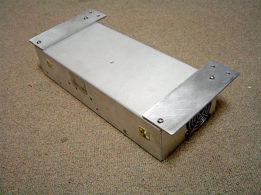 |
ECRF amplifier power supply (5/25/2007) Mounting plates attach to the back of the power supply. |
 |
ECRF preamplifier (9/10/2007) Boosts signal from VCO to 1W output |
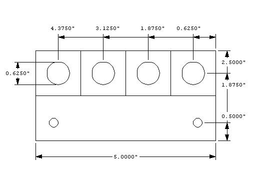 |
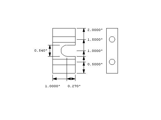
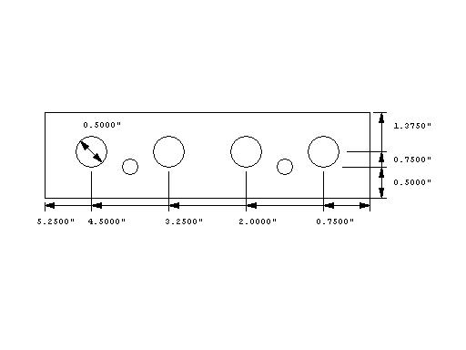
Directional coupler mount CAD (9/10/2007) |
 |
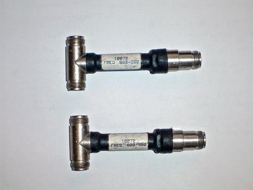
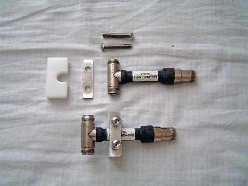
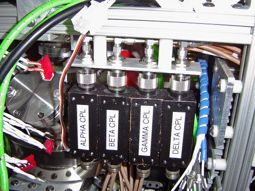
Directional couplers (9/10/2007) Measures forward and reflected power to each ion injector. Directional coupler couples -40dB. |
 |
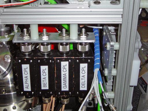
Directional couplers (9/10/2007) Attached to mounting plate. |
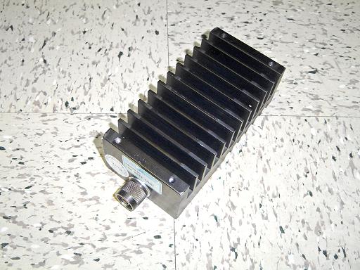 |
50 Ohm Load (2/3/2006) Decibel DB4303G 100W 50Ohm termination is used to test the RF driver in order to prevent RF interference with other equipment. |
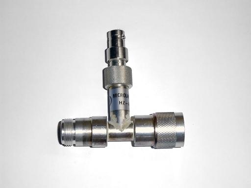 |
RF Coupler (2/25/2006) Microlab HZ-A22 provides an adjustable coupling level in order to observe high power signals on a transmission line. |
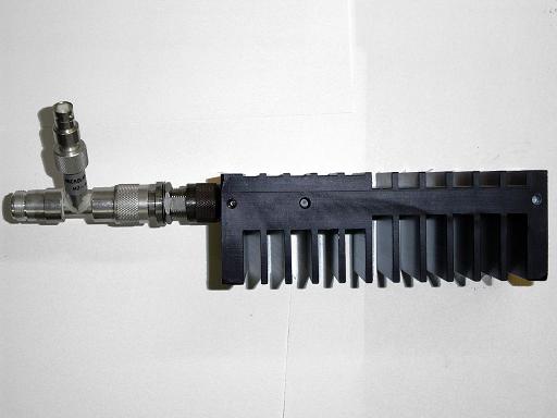 |
50 Ohm Load with Coupler (2/25/2006) Coupler is attached to 50 Ohm load so that input frequency can be monitored and verified. |
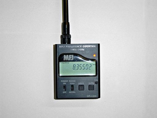 |
Frequency Counter (2/25/2006) Displays input frequency from 1MHz-3GHz. |
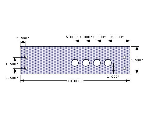 |
ECRF Input Panel (2/16/2006) Panel mount for RF input connectors for ion injectors. Type N feed through holes are 5/8" |
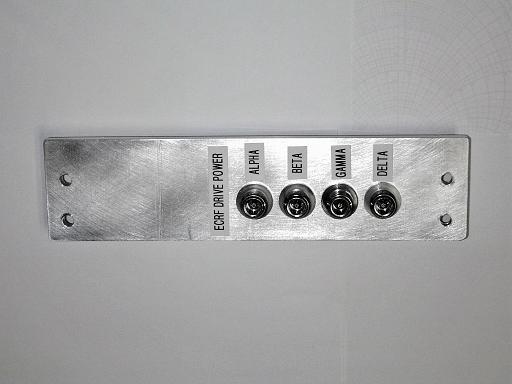 |
ECRF Input Panel (2/16/2006) ECRF input panel is machined and assembled. |
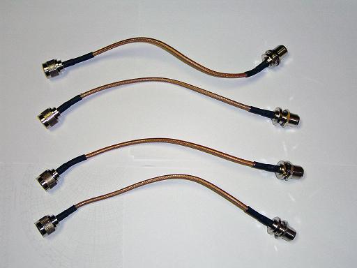 |
Type N Connector Cables (2/16/2006) RG-142 Teflon dielectric cables are used for low loss and high SWR tolerance without dielectric breakdown. |
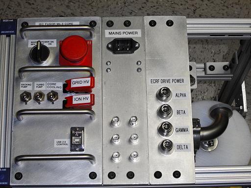 |
ECRF Input Panel (3/3/2006) ECRF input panel is mounted on reactor. |
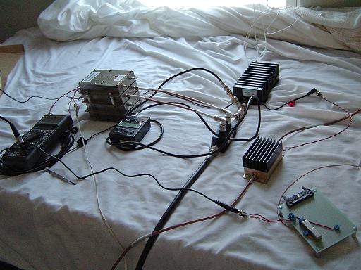 |
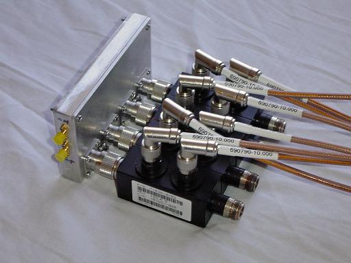
ECRF driver test (9/10/2007) Output directly from VCO is connected to input of preamplifier. Pre amp boosts RF power to about 800mW and connects to main amplifier. Main amplifier boosts signal to 42.5W and drives 50 ohm termination. Main amplifier produces maximum output power at 880MHz. |
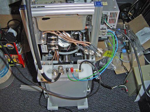 |
ECRF driver test (9/10/2007) Main amplifier attached to reactor frame. |
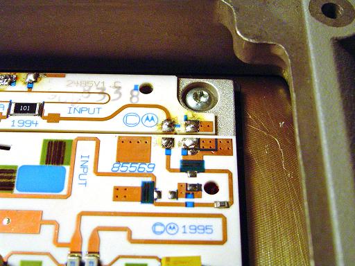 |
Splitter disconnected (9/30/2007) The input splitter and output combiner are disconnected, separating the two amplifier boards. |
 |
RF inputs connected (9/30/2007) The SMA connectors on the front panel of the amplifier are connected to the inputs of the amplifier board. |
 |
RF output connected (9/30/2007) The N connectors on the front panel of the amplifier are connected to the outputs of the amplifier board. |
 |
Amplifier boards separated (9/30/2007) The amplifier now contains two independent amplifier boards. Each board connects to an opposing pair of ion injectors through an external power splitter. |
 |
ECRF pre amp mounting plate (10/28/2007) Mounts pre amp to reactor frame. |
 |
ECRF pre amp mounting plate (10/28/2007)
|
 |
ECRF pre amps mounted (10/28/2007) Pre amps mounted to reactor frame. |
|
|
 |
Directional couplers (12/3/2007) Measures forward and reflected power to each ion injector. Directional coupler couples -40dB. |
 |
ECRF detector (10/13/2007) Detector measures output from directional coupler. Through the -40dB directional coupler the system has a sensitivity of 1/40 V/W on passing through the coupler. At 880MHz the system will have a sensitivity of 1/125 V/W. |
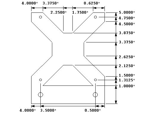 |
ECRF detector mounting plate (10/13/2007) Mounts a stack of 4 detector assemblies to reactor frame. |
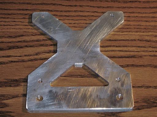 |
ECRF detector mounting plate (10/13/2007) Mounts a stack of 4 detector assemblies to reactor frame. |
 |
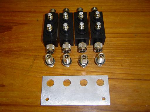
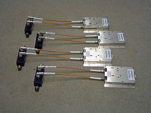
ECRF detector stack (10/28/2007) Stack of 4 detector assemblies with right angle elbows. |
ECRF detector stack mounted(10/28/2007) Mounted to reactor frame. |
|
 |
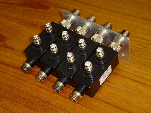
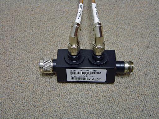
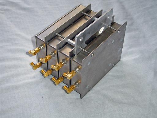
ECRF power splitter (12/3/2007) Dual power splitter/isolator for ECRF injector system. |
 |
ECRF power splitter (12/3/2007)
|
 |
ECRF power splitter (12/3/2007) Casing, type N connectors, dual power splitter/isolator, sma connectors. |
 |
ECRF power splitter (12/3/2007) 100w terminating resistors absorb power reflected back into the splitter assembly. |
 |
ECRF power splitter (12/3/2007) Coax wiring to termination resistors, SMA nd type N connectors. |
 |
ECRF power splitter (12/3/2007)
|
 |
ECRF power splitter (12/3/2007) Directional couplers mount to splitter assembly (this splitter assembly reflected too much power and was subsequently removed) |
 |
Recessed mounting block (10/28/2007) Mount amplifier to reactor frame. |
 |
Recessed mounting blocks (10/28/2007) Mount amplifier to reactor frame. |
 |
ECRF amplifier recessed (10/28/2007) Amplifier recessed into reactor frame for more compact design. |
 |
ECRF quarter wave splitter (1/20/2008) High power splitter (800-980MHz range) replaces splitter board that had high reflection. |
 |
Power splitter mount (2/15/2008) Power splitter mount and aluminum clamp
|
 |
Power splitter mount (2/15/2008) Power splitter mount and aluminum clamp |
 |
Directional coupler mounting plate (2/14/2008) Mounting plate designed for N to sma bulkhead adaptor |
 |
Directional coupler mounting plate (2/14/2008) Mounting plate attaches directional couplers to reactor frame. The use of SMA connectors allows the assembly to be positioned higher, thereby reducing space required. |
 |
Directional coupler cables (2/14/2008) SMA cables attach to coupler. |
|
|
|
|
|
|
|
|
|
|
|
|
|
|
| Useful links: http://www.fusor.net/ Open Source Fusion Research Consortium. |
|
By attempting to reproduce any experiments or devices listed on this domain in part or in whole, you agree to hold me harmless against any lawsuit or liability. Copyright © 1998 - 2005 by Andrew Seltzman. All rights reserved. |
|
| Contact me at: admin@rtftechnologies.org | |