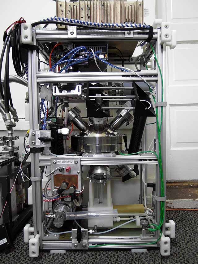
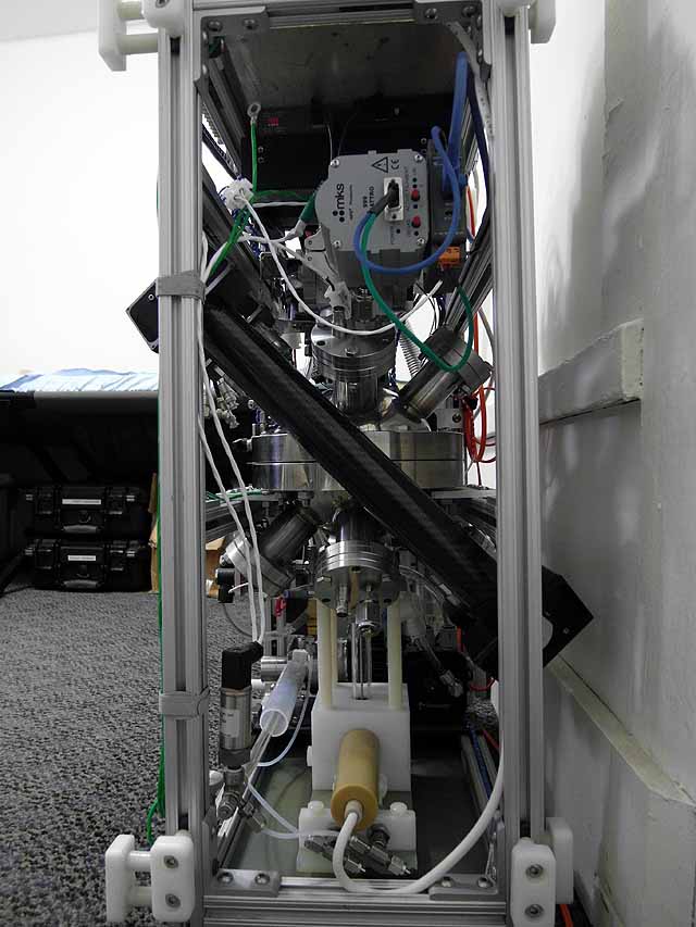
IEC Fusion Reactor Mark 3 Microbolometer
IEC Fusion Reactor Mark 3 Microbolometer |
 |
 |
 |
 |
 |
 |
 |
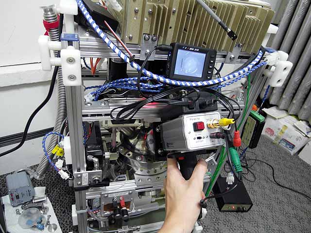
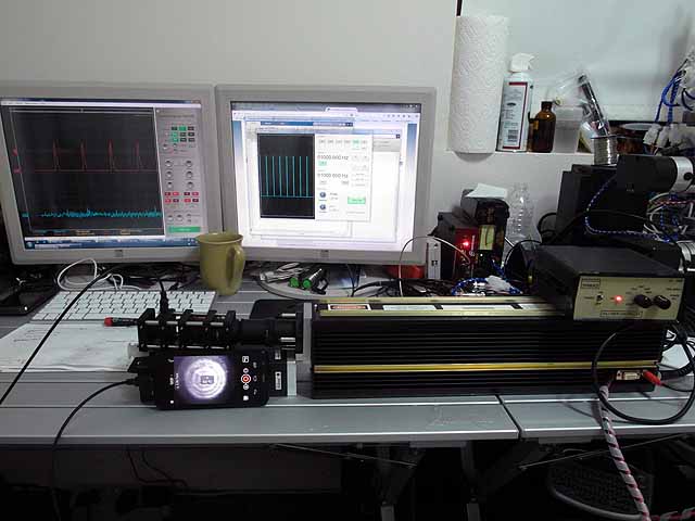
Overview: An L3 thermal eye 2500AS microbolometer (thermal imager) with 160x120 resolution and 2620AS DSP board are set up with a Zinc Selenide (ZnSe) viewport / macro lens to allow imaging of the fusor interior in the 7-14um wavelength range.
|
|
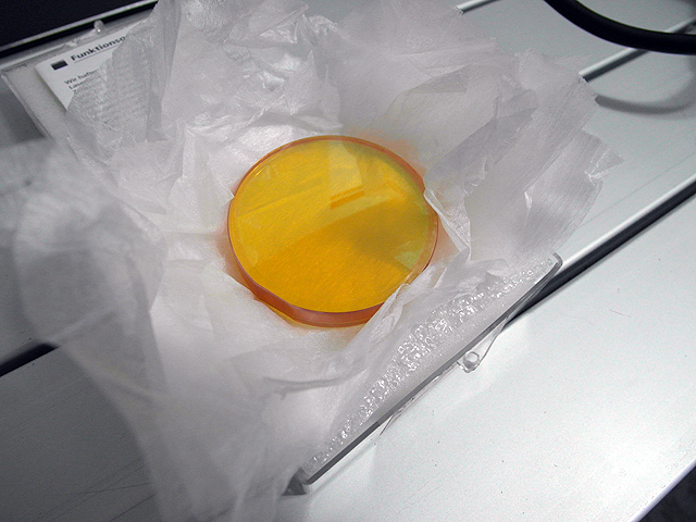 |
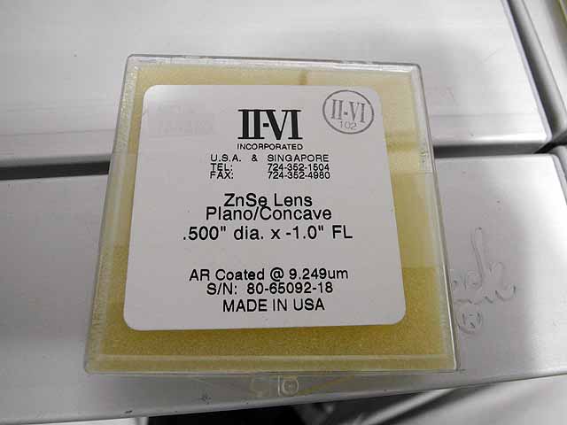
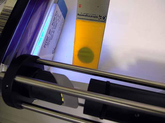
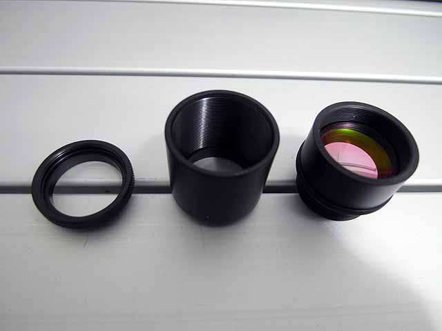
ZnSe Macro Viewport (8/22/2013) 2" OD ZnSe lens, 3/8" thick 10.5"FL |
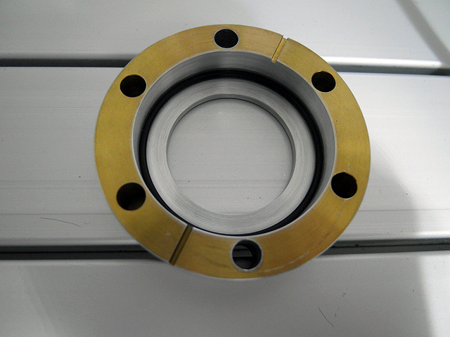 |
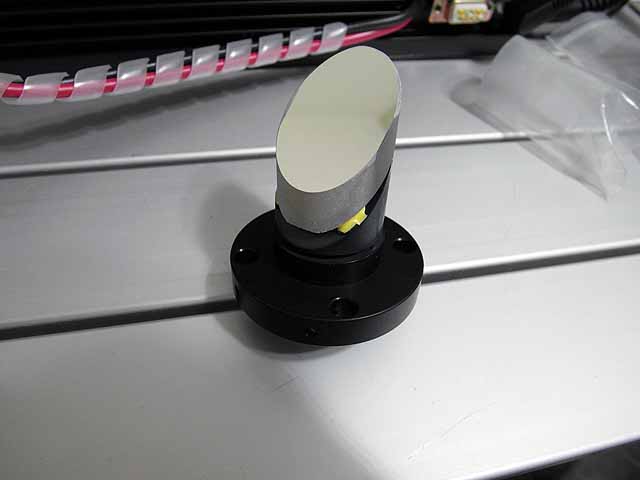
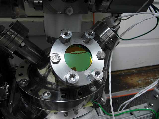
ZnSe Macro Viewport (8/22/2013) Machined aluminum CF flange to hold lens |
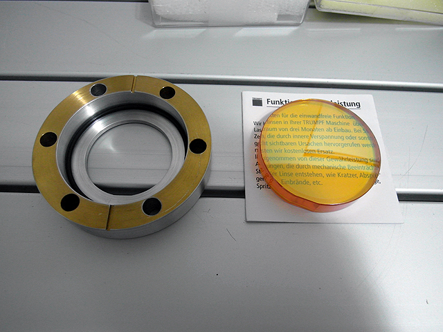 |
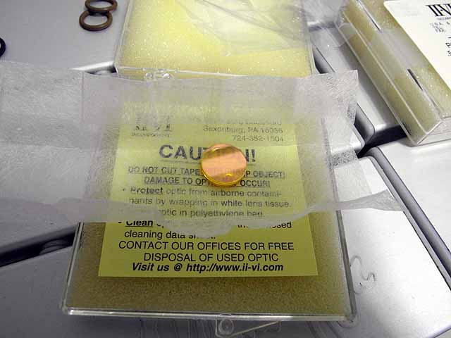
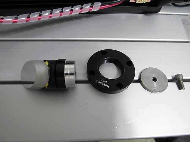
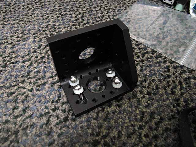
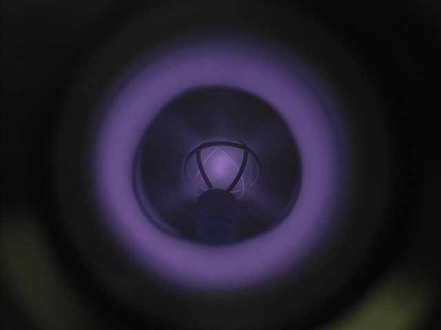
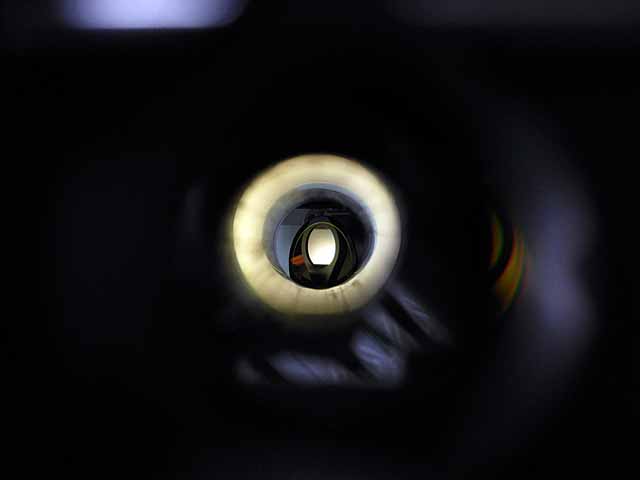
ZnSe Macro Viewport (8/22/2013) Holder and lens. |
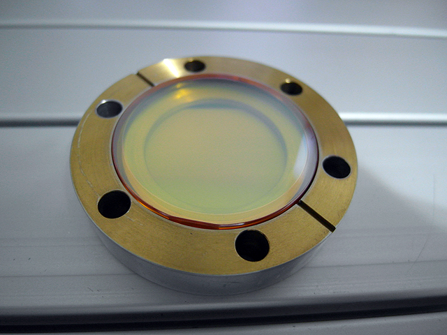 |
ZnSe Macro Viewport (8/22/2013) Lens mounted in holder |
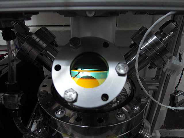 |
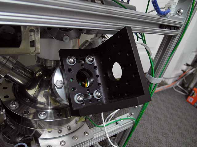
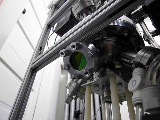
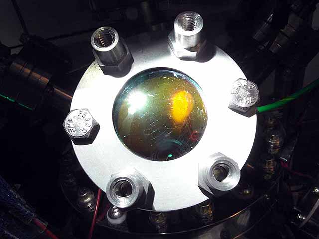
ZnSe Macro Viewport (8/22/2013) Viewport assembly mounted on fusor. |
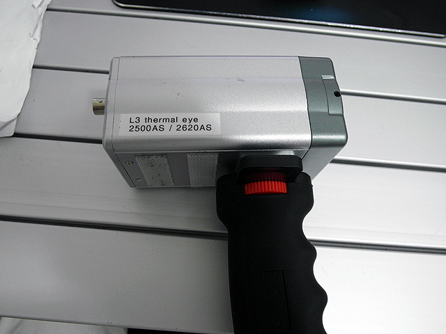 |
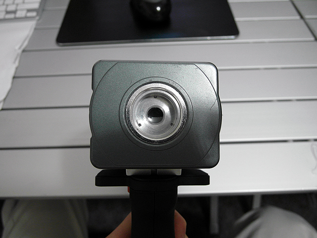
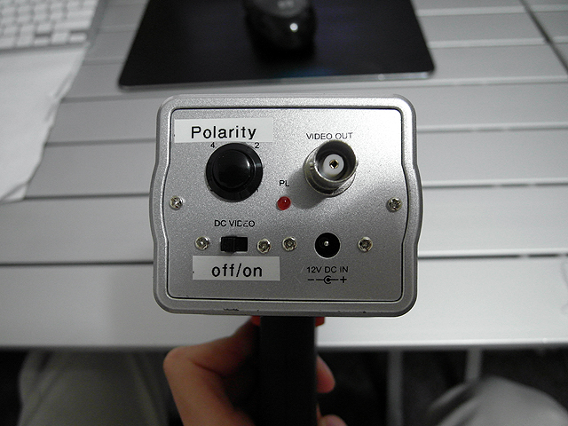
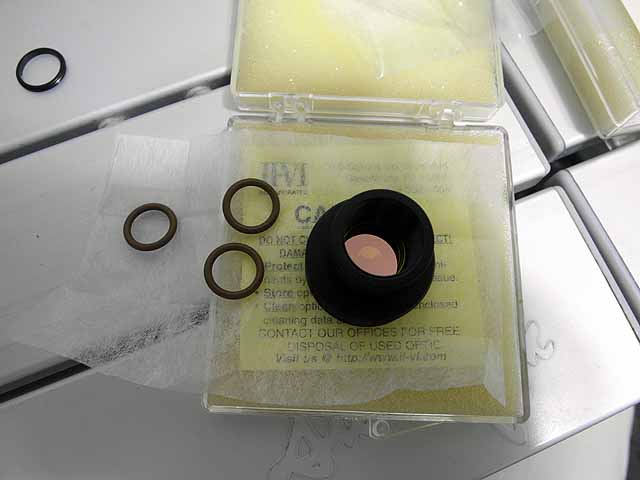
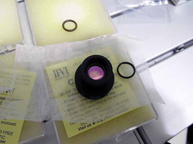
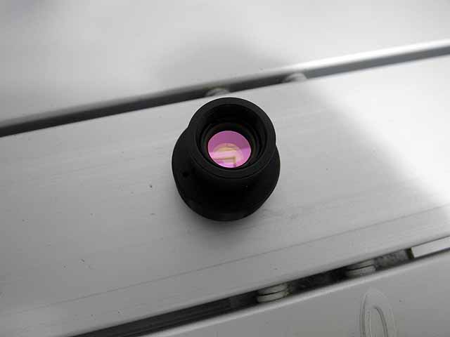
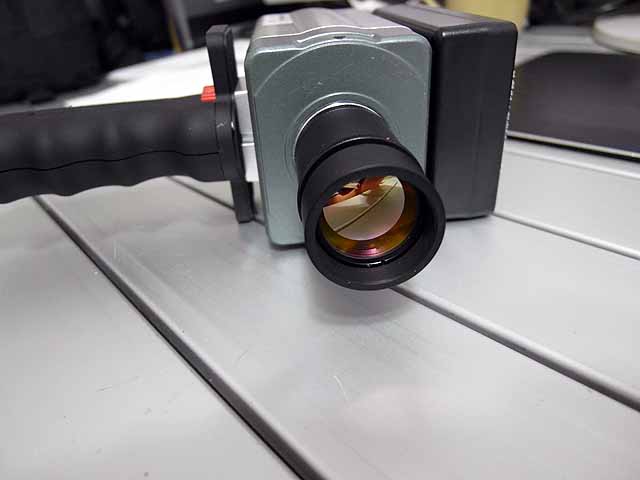
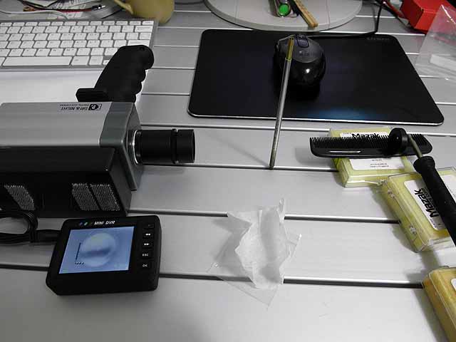
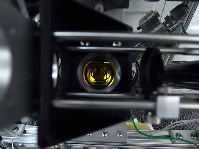
Thermal imager (8/22/2013) Thermal eye 2500AS core mounted in a camera case |
 |
Thermal imager (8/22/2013) Thermal eye 2500AS core mounted in a camera case |
 |
Thermal imager (8/22/2013) Thermal eye 2500AS core mounted in a camera case |
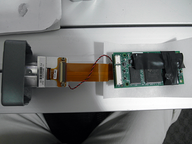 |
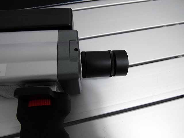
Thermal imager (8/22/2013) Core and DSP board |
 |
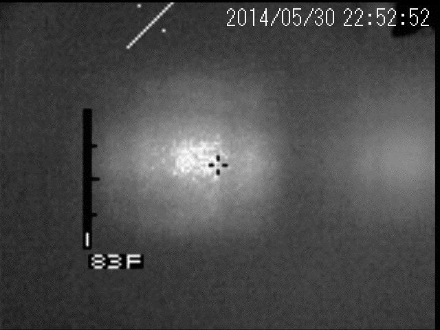
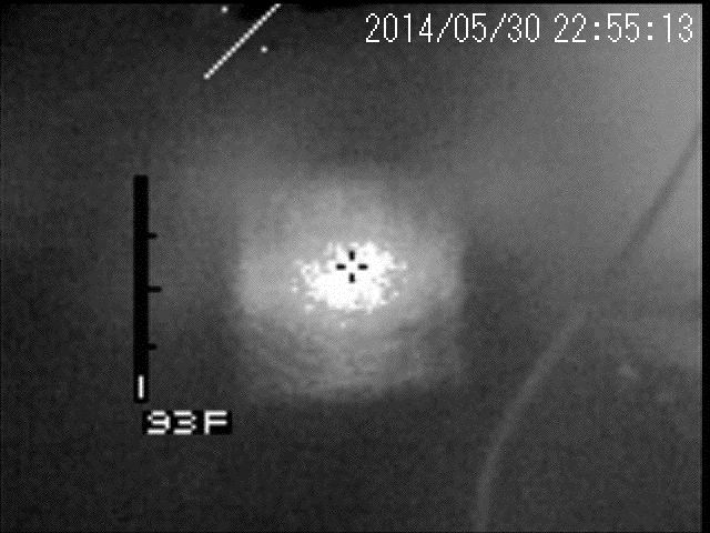
Thermal imager (8/22/2013) Grid after a short uncooled test. |
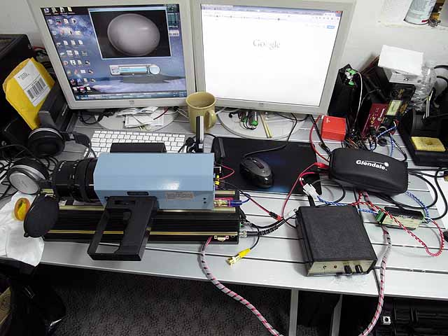 |
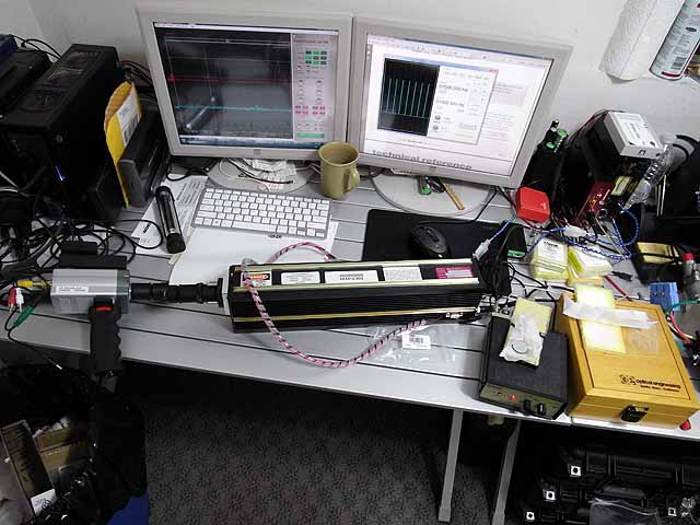
Thermal imager (5/24/2014) Preliminary tests with co2 laser and ISI 77 thermal imager |
 |
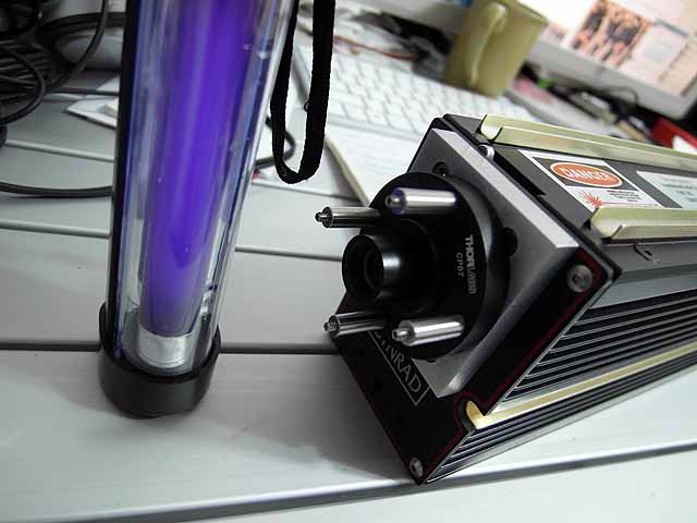
Thermal imager (5/24/2014) Laser controller |
 |
Thermal imager (5/24/2014) Preliminary tests with co2 laser and ISI 77 thermal imager |
 |
Thermal imager (5/24/2014) Preliminary tests with co2 laser and ISI 77 thermal imager |
Thermal imager (5/24/2014) Beam through diverging lens onto wall imaged with ISI-77 thermal camera. |
|
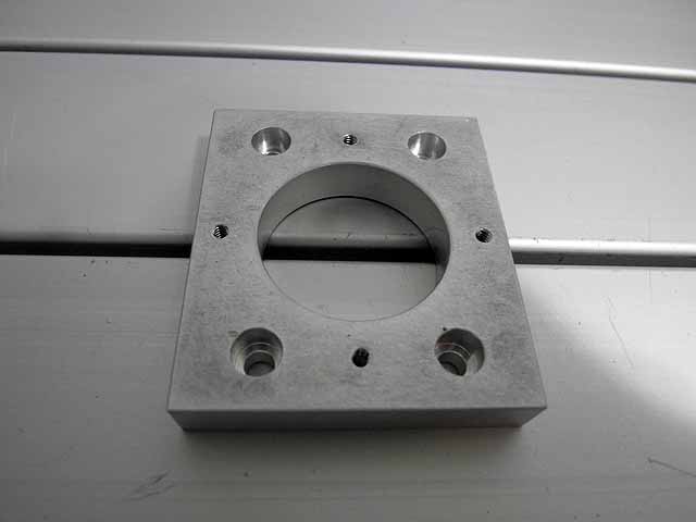 |
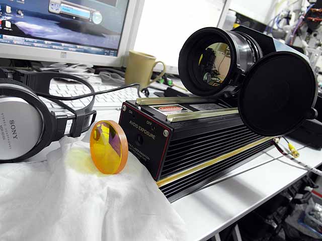
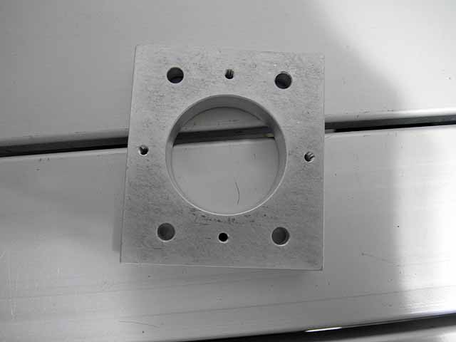
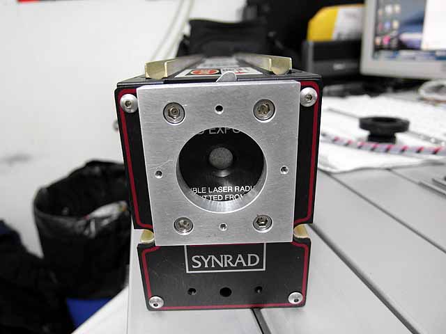
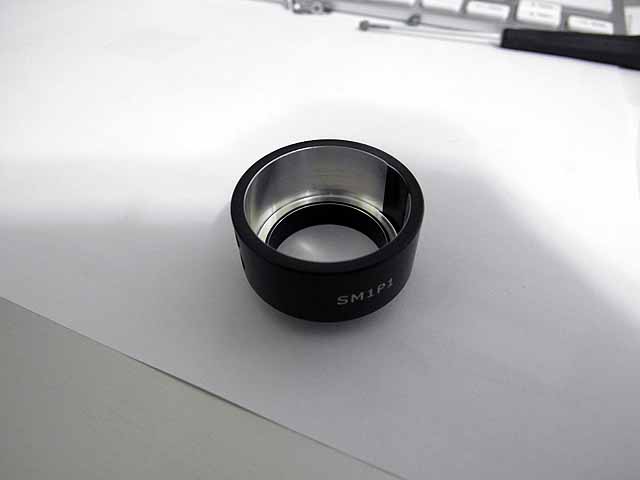
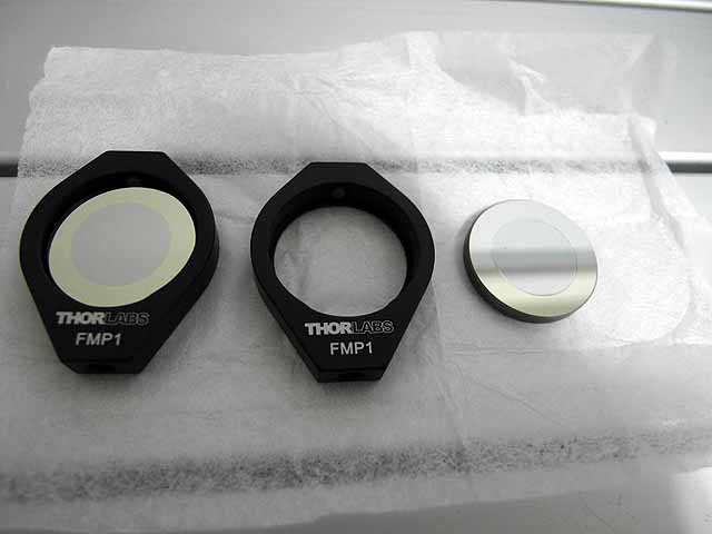
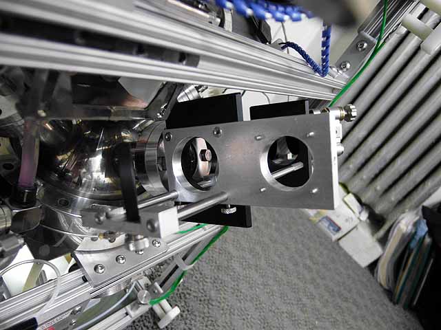
CO2 Laser (7/4/2014) Face plate adapter to 30mm thorlabs cage system. |
 |
CO2 Laser (7/4/2014) Face plate adapter to 30mm thorlabs cage system. |
 |
CO2 Laser (7/4/2014) Face plate adapter to 30mm thorlabs cage system. |
 |
CO2 Laser (7/4/2014) Face plate adapter to 30mm thorlabs cage system. |
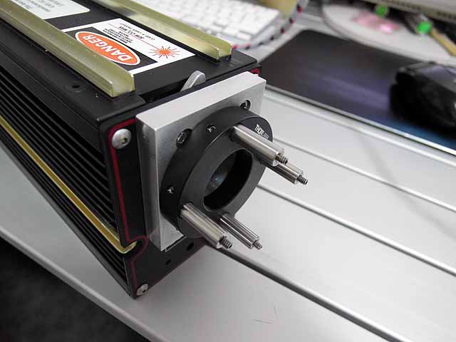 |
CO2 Laser (7/4/2014) Face plate adapter to 30mm thorlabs cage system. |
 |
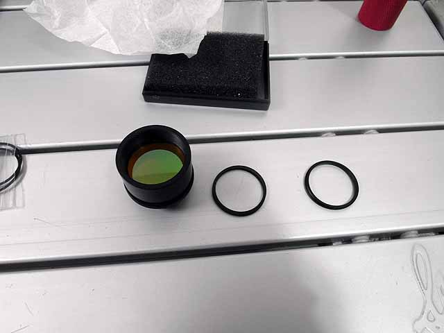
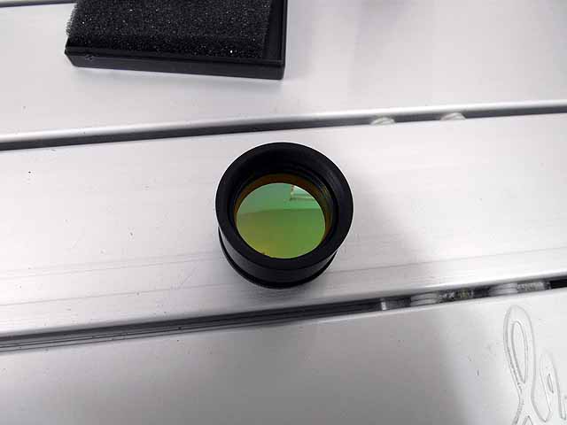
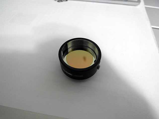
CO2 Laser (7/4/2014) ZnSe diverging lens |
 |
CO2 Laser (7/4/2014) ZnSe diverging lens |
 |
CO2 Laser (7/4/2014) ZnSe diverging lens |
 |
CO2 Laser (7/4/2014) ZnSe diverging lens, stack of 2 |
 |
CO2 Laser (7/4/2014) ZnSe diverging lens, stack of 2 |
 |
CO2 Laser (7/4/2014) ZnSe diverging lenses and UV lamp for thermal image plate |
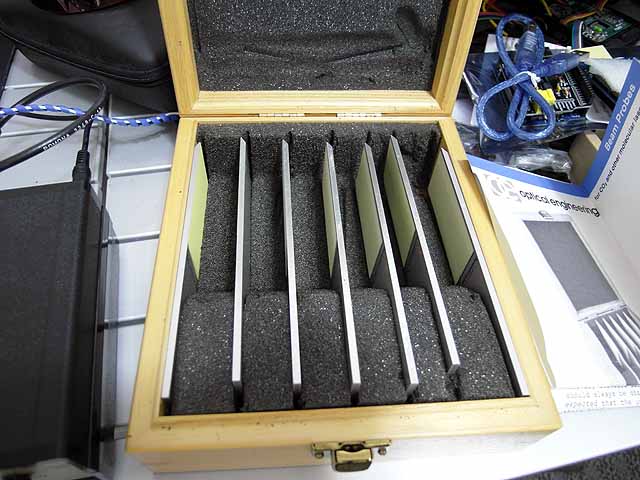 |
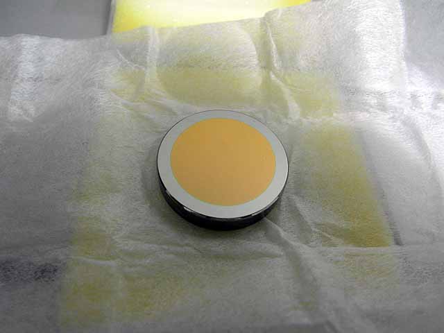
CO2 Laser (7/4/2014) Thermal image plate set |
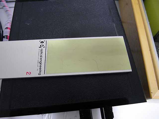 |
CO2 Laser (7/4/2014) Thermal image plate |
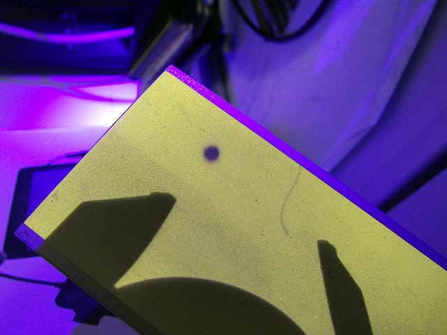 |
CO2 Laser (7/4/2014) Thermal image plate with unexpanded laser beam. |
|
CO2 Laser (7/4/2014) Unexpanded beam viewed on thermal image plate |
|
CO2 Laser (7/4/2014) Unexpanded beam viewed on thermal image plate |
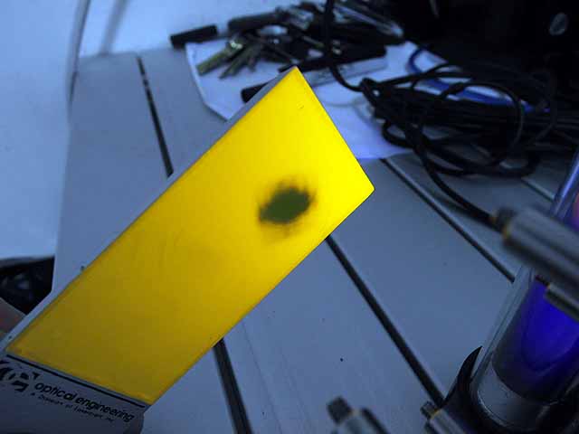 |
CO2 Laser (7/4/2014) Expanded beam viewed on thermal image plate |
 |
CO2 Laser (7/4/2014) Expanded beam viewed with thermal-eye 2500 thermal imager |
 |
CO2 Laser (7/4/2014) Expanded beam viewed with thermal-eye 2500 thermal imager |
Thermal imager (7/4/2014) Beam through diverging lens onto wall imaged with L3 thermal-eye 2500 thermal camera. |
|
Thermal imager (7/4/2014) Beam through diverging lens onto wall imaged with L3 thermal-eye 2500 thermal camera. |
|
Thermal imager (7/4/2014) Beam through diverging lens onto wall imaged with L3 thermal-eye 2500 thermal camera. |
|
Thermal imager (7/4/2014) Beam through diverging lens onto wall imaged with L3 thermal-eye 2500 thermal camera. |
|
 |
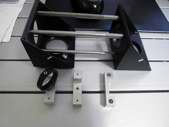
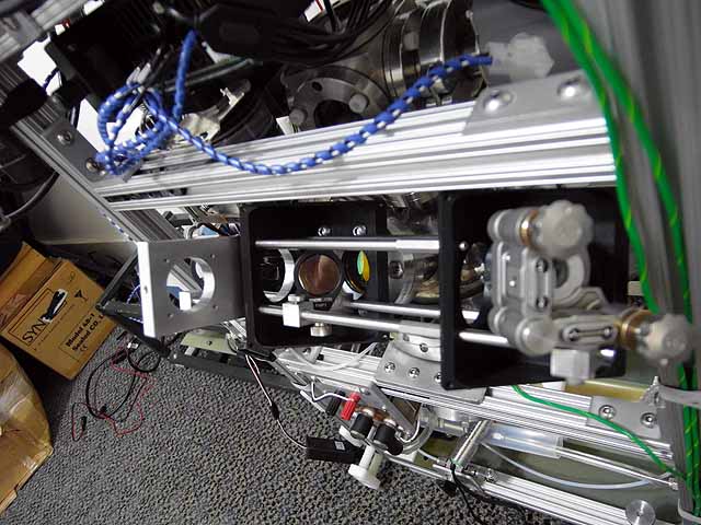
CO2 Laser (7/4/2014) Beam expander system |
 |
CO2 Laser (7/4/2014) Beam expander system |
 |
CO2 Laser (7/4/2014) Beam expander system |
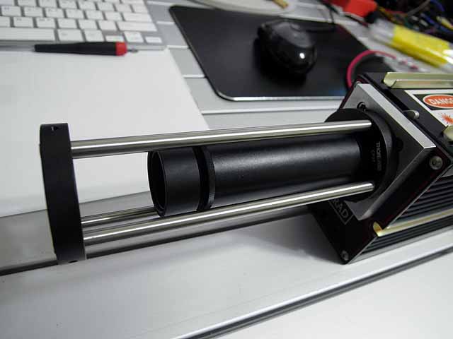 |
CO2 Laser (7/4/2014) Beam expander system with extended cage |
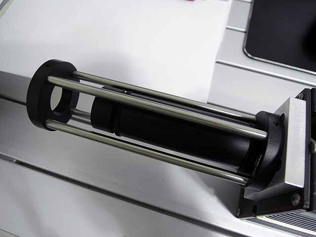 |
CO2 Laser (7/4/2014) Beam expander system with extended cage |
 |
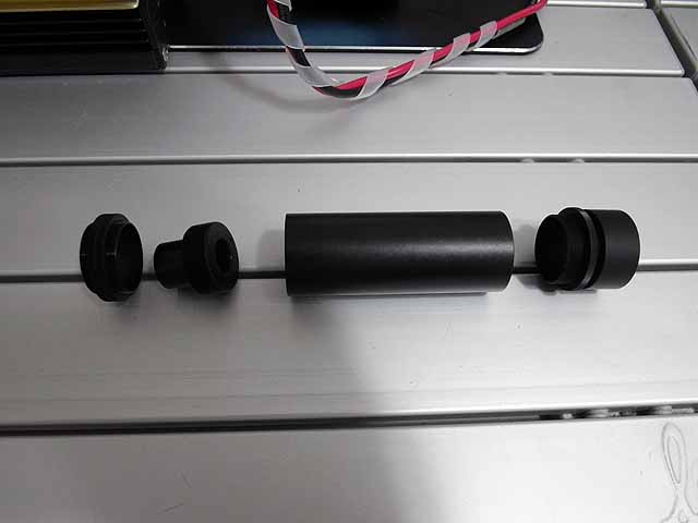
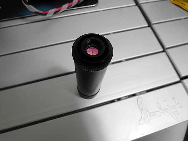
CO2 Laser (7/7/2014) Beam expander output lens, tube, and spacers. |
 |
CO2 Laser (7/7/2014) Beam expander output lens, tube, and spacers. |
 |
CO2 Laser (7/7/2014) Beam expander output lens, tube, and spacers. |
 |
CO2 Laser (7/7/2014) Beam expanded by 6x, now parallel |
 |
CO2 Laser (7/7/2014) Beam expanded by 6x, now parallel |
Thermal imager (7/7/2014) Beam through 6x beam expander onto wall imaged with L3 thermal-eye 2500 thermal camera. |
|
Thermal imager (7/7/2014) Beam through 6x beam expander onto wall imaged with L3 thermal-eye 2500 thermal camera. |
|
|
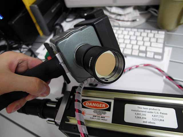
Thermal imager (7/4/2014) T=30% germanium output coupler with L3 thermal-eye 2500 thermal camera. |
 |
CO2 Laser (7/12/2014) Beam dump |
 |
CO2 Laser (7/12/2014) Beam dump |
|
Thermal imager (7/12/2014) 9x expanded beam in beam dump |
 |
CO2 Laser (7/12/2014) Beam expanded to 9x on thermal image plate |
 |
CO2 Laser (7/12/2014) Right angle turning mirror and cage mount |
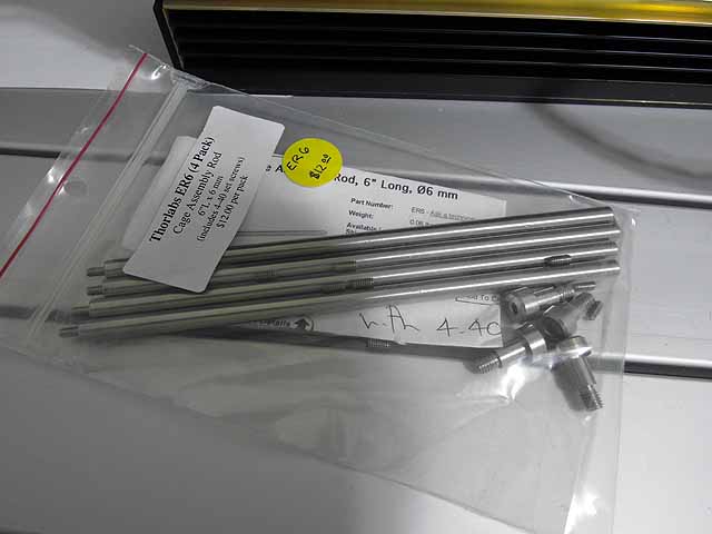 |
CO2 Laser (7/12/2014) Cage rods |
 |
CO2 Laser (7/12/2014) Right angle turning mirror and cage mount |
 |
CO2 Laser (7/12/2014) Right angle turning mirror and cage mount |
 |
CO2 Laser (7/12/2014) Beam expanded to 9x, reflected with turning mirror, and displayed on thermal image plate |
 |
CO2 Laser (7/12/2014) Core output lens |
 |
CO2 Laser (7/12/2014) Right angle mount |
 |
CO2 Laser (7/12/2014) Right angle mount on core output lens |
 |
CO2 Laser (7/12/2014) Core input lens |
Thermal imager (7/12/2014) Beam through 9x beam expander onto wall imaged with L3 thermal-eye 2500 thermal camera. |
|
 |
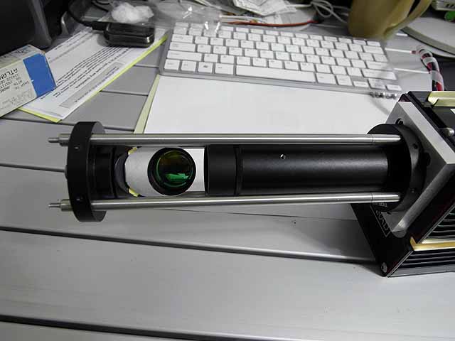
Thermal imager (7/17/2014) Beam expander assembly to reduce beam to size of optical detector |
 |
Thermal imager (7/17/2014) Beam expander assembly to reduce beam to size of optical detector |
 |
Thermal imager (7/17/2014) Beam expander assembly to reduce beam to size of optical detector |
 |
Thermal imager (7/17/2014) Test setup, soldering iron as heat source collimated through germanium lens |
 |
Thermal imager (7/17/2014) Shadow viewed on detector |
 |
CO2 Laser (7/19/2014) Output beam without iris fully open |
 |
CO2 Laser (7/19/2014) Output beam without iris clipping edges of beam between two lenses in beam expander |
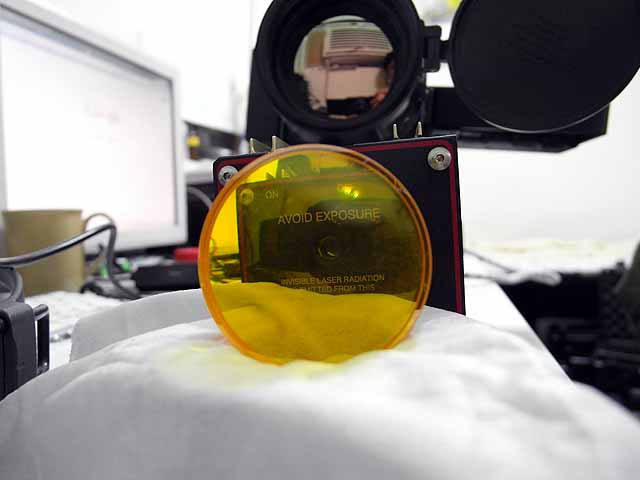
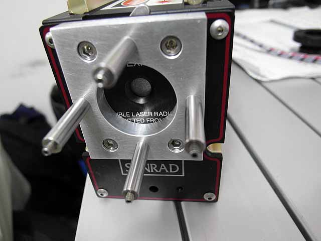
CO2 Laser (7/19/2014) Synrad H48-1 with a 9x beam expander that has an internal adjustable iris to prevent reflection of the over expanded beam off the internal walls of the lens tube that cause a halo around the primary beam. Imaged with a thermal eye 2500AS |
|
 |
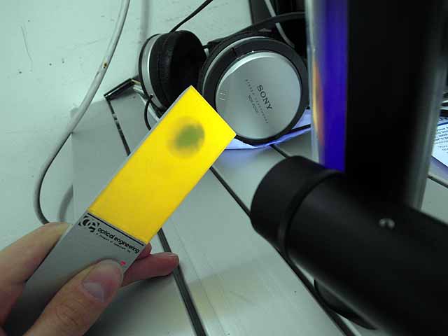
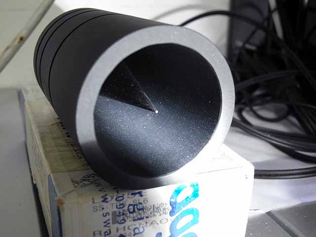
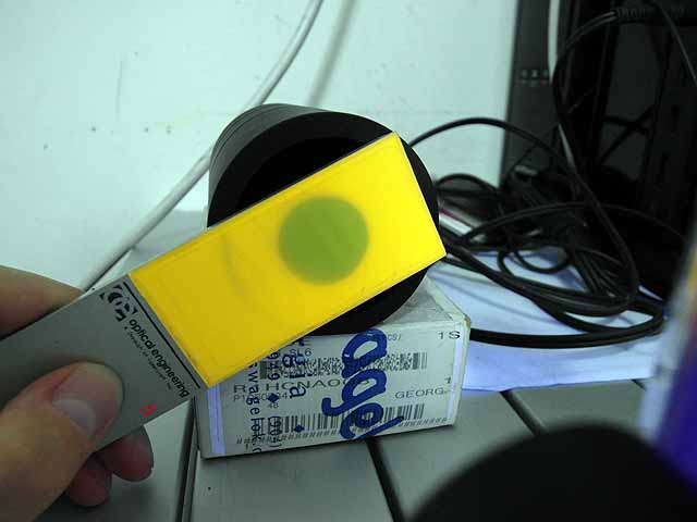
Thermal imager (7/19/2014) Germanium rear coupler 99.5% reflective (200x attenuation of beam) |
 |
Thermal imager (7/19/2014) Mount for coupler to adapt to thorlabs 1" tube |
 |
Thermal imager (7/19/2014) Germanium rear coupler in mount |
 |
Thermal imager (7/19/2014) Germanium rear coupler mounted on thermal imager for 200x beam attenuation |
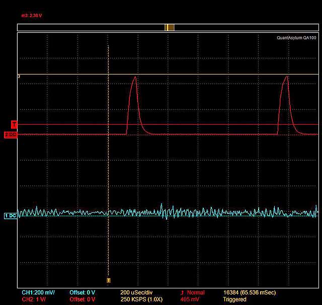 |
Thermal imager (7/19/2014) Laser modulation waveform from arbitrary waveform generator, 1khz square wave 6% duty cycle |
 |
Thermal imager (7/19/2014) Laser test setup with arbitrary waveform generator controlling laser |
 |
Thermal imager (7/19/2014) Shadow in laser beam |
 |
Thermal imager (7/19/2014) Shadow in laser beam |
Thermal imager (7/19/2014) Synrad H48-1 with a 9x beam expander bench test. Shadow from soldering iron tip cast in beam. Imaged with a thermal eye 2500AS, 99.5% reflective rear coupler from laser cutter used as 200x attenuator, laser run at ~20% power and 1kHz square wave with 6% duty cycle. |
|
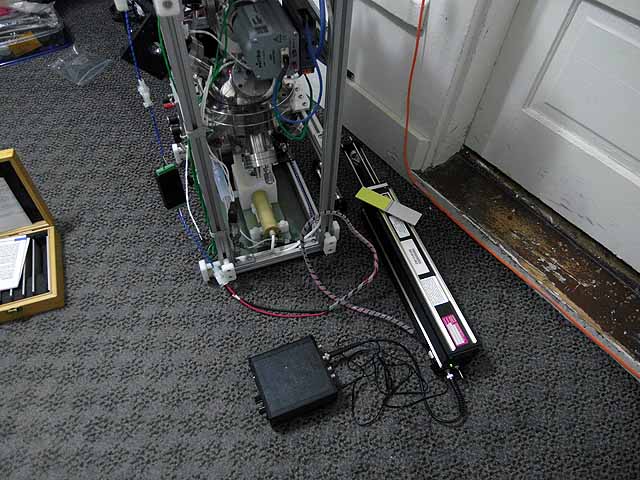 |
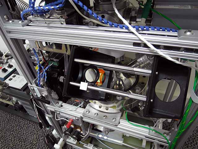
Laser setup (7/19/2014) Laser positioned next to fusor |
 |
Laser setup (7/19/2014) Beam aligned with input window |
 |
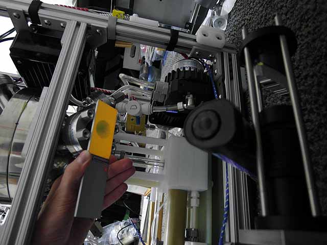
Laser setup (7/19/2014) Thermal imager looking through output window |
 |
Laser setup (7/19/2014) Shadow cast by central grid |
 |
Laser setup (7/19/2014) Shadow cast by central grid |
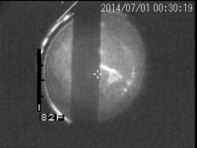
Laser setup (7/19/2014) Synrad H48-1 with a 9x beam expander projected through IEC fusor core with no plasma. Shadow from ion accelerating grid cast in beam. Imaged with a thermal eye 2500AS, 99.5% reflective rear coupler from laser cutter used as 200x attenuator, laser run at ~20% power and 1kHz square wave with 6% duty cycle. |
|
 |
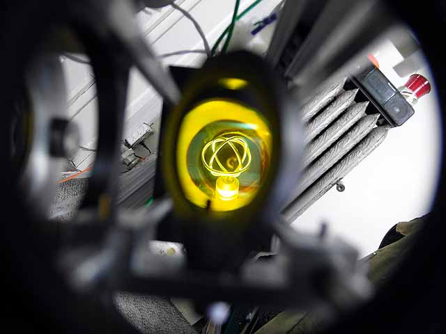
Fusor setup (7/30/2014) Plasma operation with 4 ion sources |
 |
Fusor setup (7/30/2014) Plasma operation with 4 ion sources |
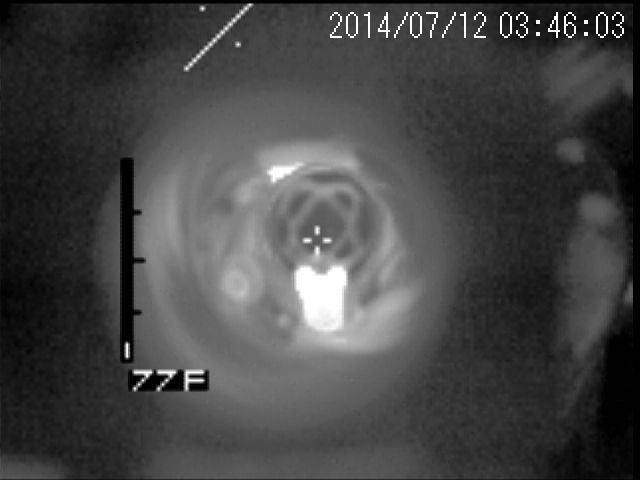 |
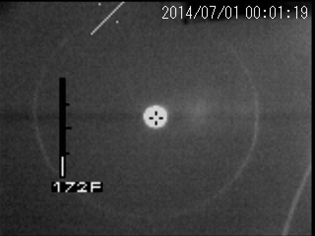
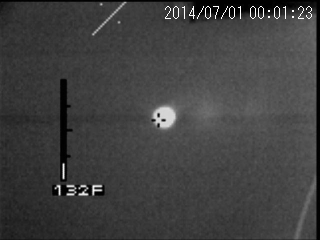
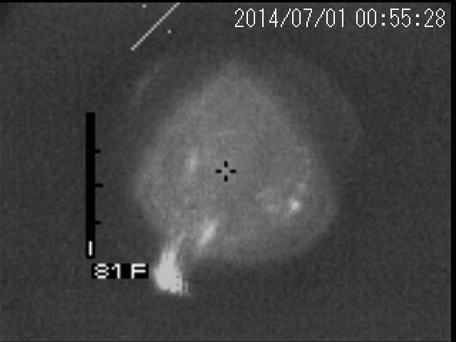
Thermal imager (7/30/2014) Grid with coolant flow on |
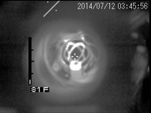 |
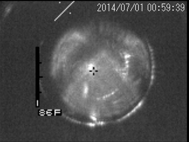
Thermal imager (7/30/2014) Grid after several seconds with coolant flow off |
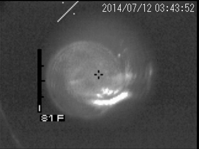 |
Laser test (7/30/2014) 10.6um beam through plasma, no attenuation seen. |
 |
Plasma (8/24/2014) Image of plasma at 5mTorr |
Thermal imager (8/24/2014) 320x240 resolution thermal imaging of IEC fusor grid with coolant flow on and off |
|
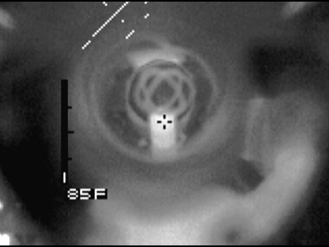
Thermal imager (8/24/2014) 160x120 resolution thermal imaging of IEC fusor grid with coolant flow on and off with temperature readout |
|
Thermal imager (8/24/2014) 320x240 resolution thermal imaging of IEC fusor interior |
|
Thermal imager (8/24/2014) 160x120 resolution thermal imaging of IEC fusor grid insulator |
|
 |
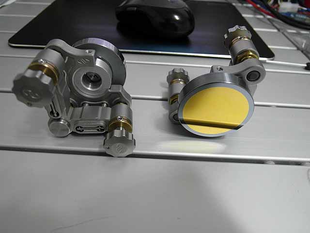
Interferometer (8/29/2014) T=30% germanium mirror and mirror mount |
 |
Interferometer (8/29/2014) Mirror mount and beam guide. |
 |
Interferometer (8/29/2014) Mounted on core |
 |
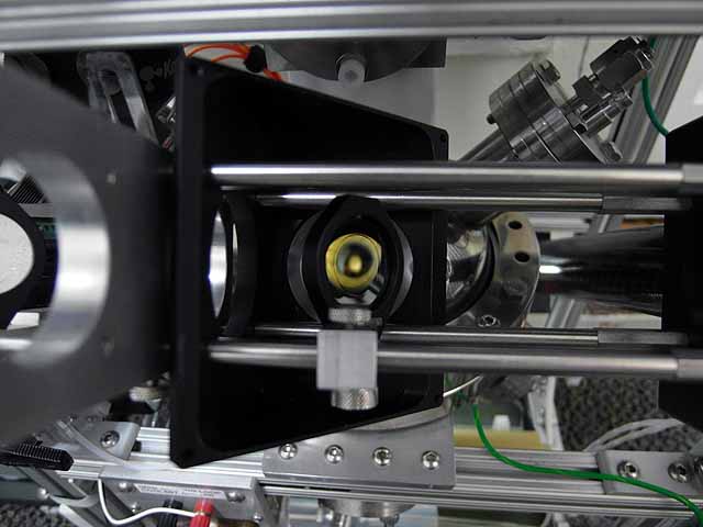
Interferometer (8/29/2014) View of grid reflected off of mirror |
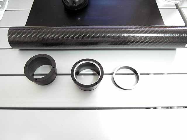 |
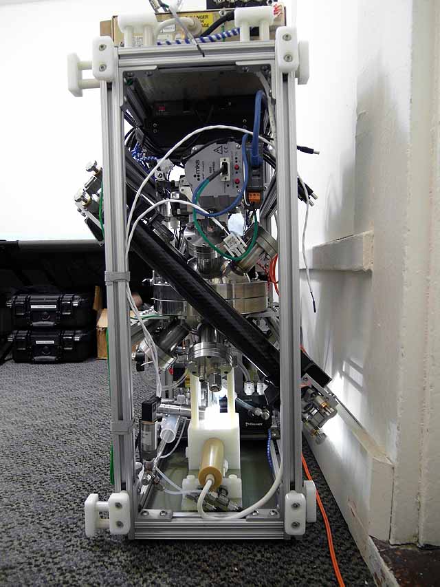
Interferometer (8/29/2014) Carbon fiber tube to stiffen interferometer reference beam arm |
 |
Interferometer (8/29/2014) Carbon fiber tube to stiffen interferometer reference beam arm |
 |
Interferometer (8/29/2014) Carbon fiber tube to stiffen interferometer reference beam arm |
 |
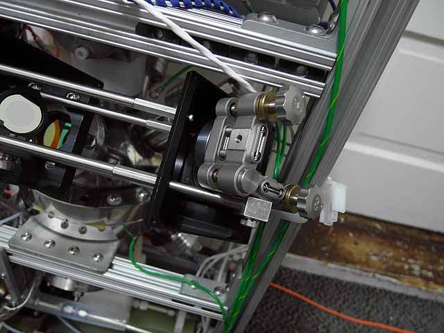
Interferometer (8/29/2014) Turning mirrors and mounts. Mirrors are 1.75x0.375" gold coated silicon. |
 |
Interferometer (9/19/2014) Turning mirrors and mounts. Adapter to optics cage system |
 |
Interferometer (9/19/2014) Mirrors mounted on optics cage |
 |
Interferometer (9/19/2014) Mirrors mounted on optics cage |
 |
Interferometer (9/19/2014) Mirrors mounted on optics cage |
 |
Interferometer (9/19/2014) View of laser beam splitter through reference arm. |
 |
Interferometer (9/19/2014) View of laser beam splitter through reference arm. Close up. |
 |
Interferometer (9/19/2014) View of laser beam splitter through measurement arm. |
 |
Interferometer (9/19/2014) Thermal imager mount and adapter to 30mm thorlabs cage system. |
 |
Interferometer (9/19/2014) Thermal imager mount and adapter to 30mm thorlabs cage system. |
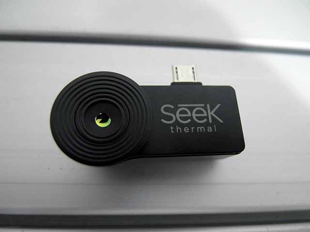 |
Interferometer (11/8/2014) Seek thermal imager |
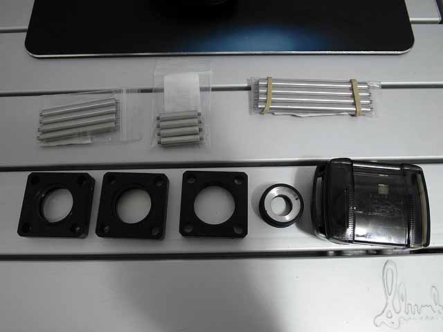 |
Interferometer (11/8/2014) Adapter to mount to thorlabs cage system. |
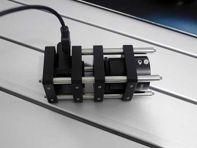 |
Interferometer (11/8/2014) Seek thermal imager mounted on thorlabs cage with beam condensor and 200x power attenuator |
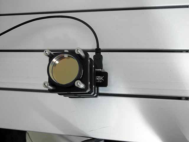 |
Interferometer (11/8/2014) 200x power attenuator |
 |
Interferometer (11/8/2014) Imaging CO2 laser beam ~5W, 1kHz, 6% duty cycle |
 |
Interferometer (11/8/2014) Imaging CO2 laser beam |
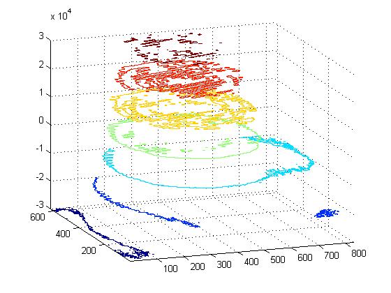 |
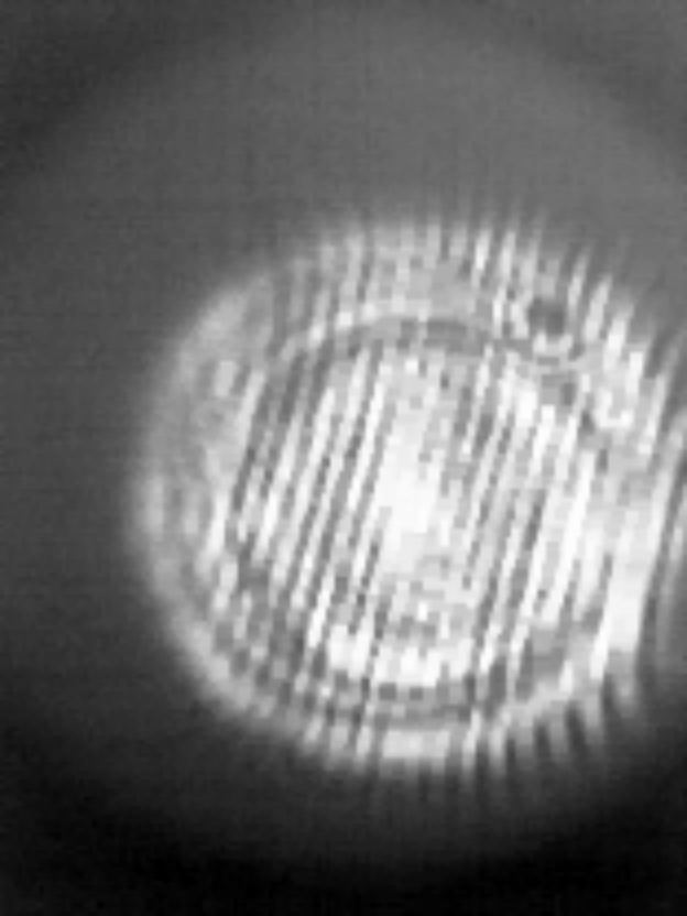
Interferometer (11/8/2014) Beam profile |
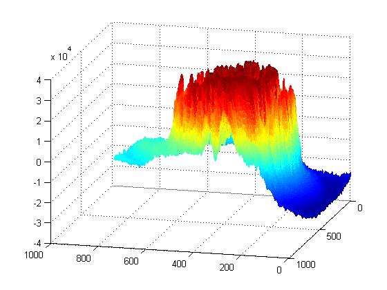 |
Interferometer (11/8/2014) Beam profile |
 |
Interferometer (5/1/2016) Some burn inon the inside coating of the ZnSe viewports was observed when running with deuterium(doesn't happen with air). The D- ions comming from the grid are not readily deflected by the magnetic beam deflectors. |
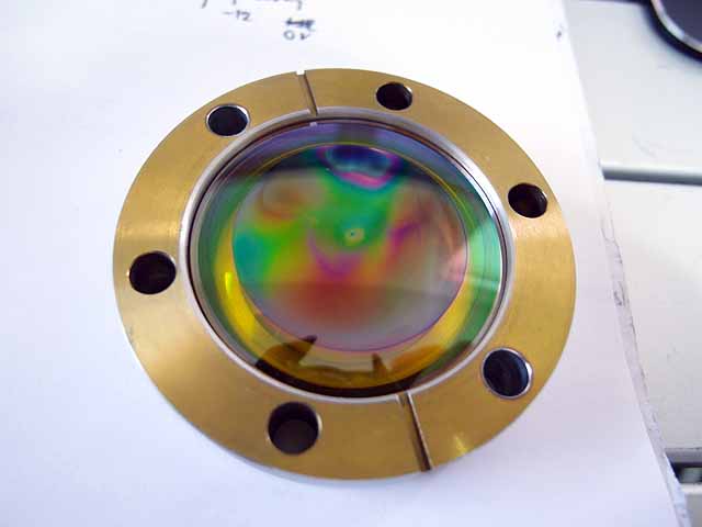 |
Interferometer (5/1/2016) The ZnSe windows have been removed and the damage analyzed. Both top and bottom windows showed deposition from sputtering considerably more visible then that on the glass viewports. |
 |
Interferometer (5/1/2016) This is likely due to the deposited material interfering with the BBAR(broad band antireflective) dielectric coating on the window causing considerably more change in transmitted light. |
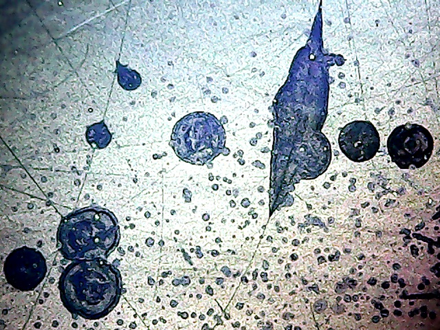 |
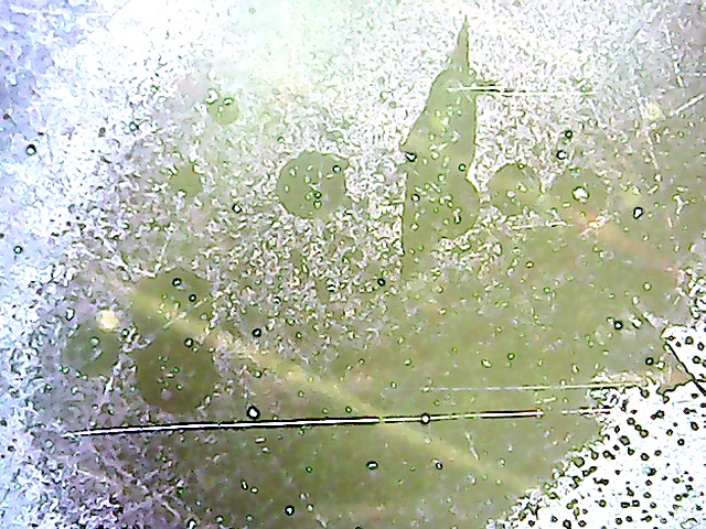
Interferometer (5/1/2016) Examination of the window surface under a microscope showed pitting of the BBAR coating where the D- beam was hitting the window. |
 |
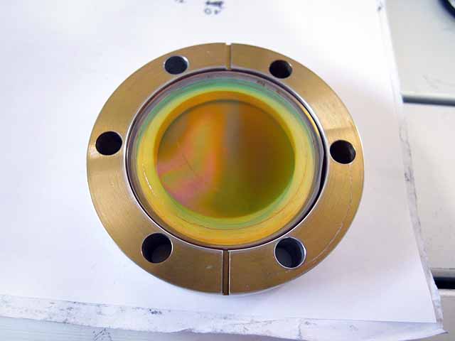
Interferometer (5/1/2016) Subsequent cleaning of the window was able to remove most of the BAR coating(and the deposition with it). Post cleaning the window is transparent again. None of the pitting or damage extends into the ZnSe material, it appears only the BBAR coating is strongly affected by D- bombardment, however to err on the side of safety, the ZnSe windows were not re-installed to prevent any potential sputtering of zinc from the now unprotected window surface into the vacuum system. |
Interferometer (5/1/2016)
|
|
| Useful links:http://www.fusor.net/ Open Source Fusion Research Consortium. | |
By attempting to reproduce any experiments or devices listed on this domain in part or in whole, you agree to hold me harmless against any lawsuit or liability. Copyright © 1998 - 2005 by Andrew Seltzman. All rights reserved. |
|
| Contact me at: admin@rtftechnologies.org | |