| Electrostatic Particle Accelerator Construction |
 |
 |
 |
 |
 |
 |
 |
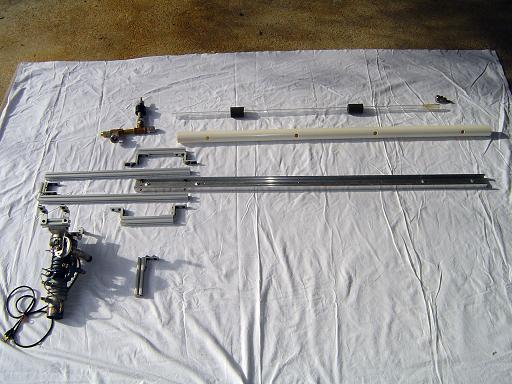
| Particle accelerator construction pictures: Due to the accelerators modular design, the entire system can be dismantled and then re-assembled within an hour. This was done, and pictures of the construction process were documented. |
|
|
|
Accelerator parts:
|
|
|
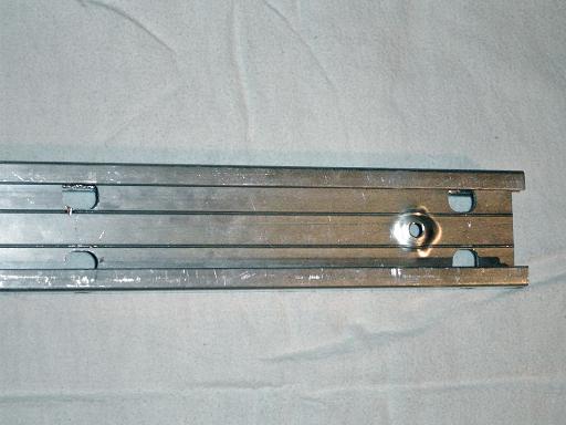
I channel front: Holes are cut in the i channel surface for t-nuts. |
|
|
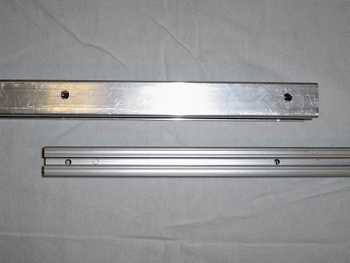
I channel mounting: Holes are drilled in the i channel sides for connection bolts. Holes in the 8020 are for tightening the bolts via an allen key. |
|
|
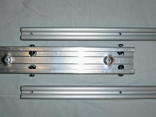
Connection bolts: Connection bolts are inserted into the holes and t-nuts are attached. |
|
|
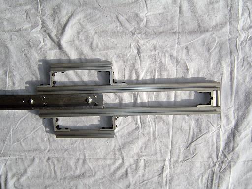
Assembled frame: Bolt heads slide into the channels in the 8020 and are tightened with an allen key. Handles and spacers are attached. |
|
|
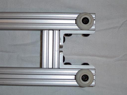
Front spacer: Front spacer is attached to maintain proper separation between the 8020 extrusions. |
|
|
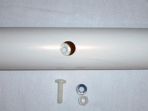
Beam line shield: Holes are drilled into the PVC shield for mounting to the frame. |
|
|
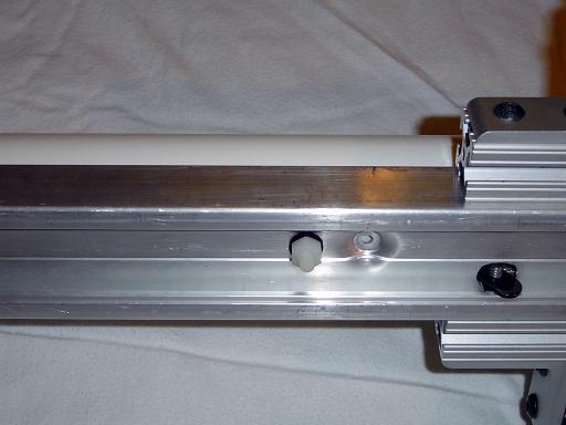
Shield attachment: Shield mounts to the frame with nylon bolts. |
|
|
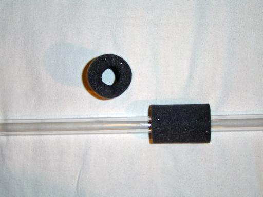
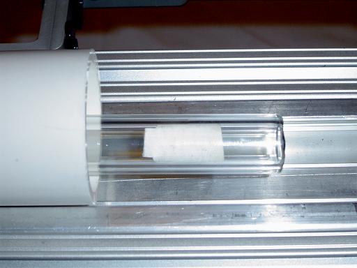
Beam line and spacers: Glass beam line is outfitted with foam spacers to center it within the shield. |
|
|
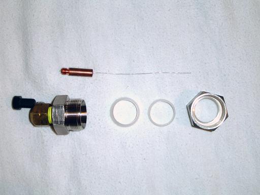
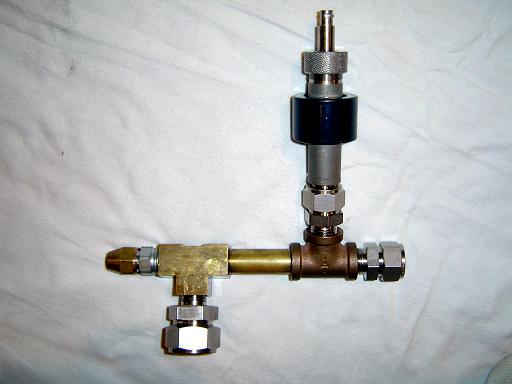
Cathode parts: Cathode assembly consists of a fine platinum wire held in the swagelok fitting by a welding tip. |
|
|
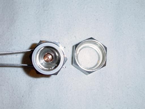
Cathode Assembled:
|
|
|
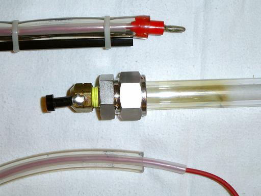
Cathode and connector: Cathode mounts to glass beam line and seals via the teflon ferrules. The HV cable consists of a voltmeter wire within a vinyl tube within a rubber tygon tube. The cable connects to the cathode with a banana plug soldered to the brass cap on the end of the swagelok. |
|
|
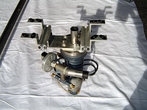
Diffusion pump: The diffusion pump mounts to the bottom of the frame and provides the high vacuum capability as well as physical support to the vacuum hub.
|
|
|
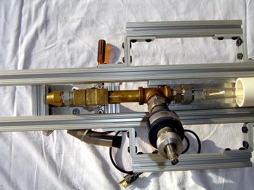
Vacuum hub: Vacuum hub connects the beam line to the diffusion pump and penning gauge. |
|
|
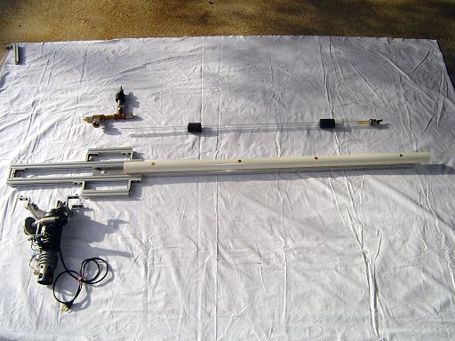
Main components: Frame, beam line, vacuum hub, and diffusion pump ready for connection. |
|
|
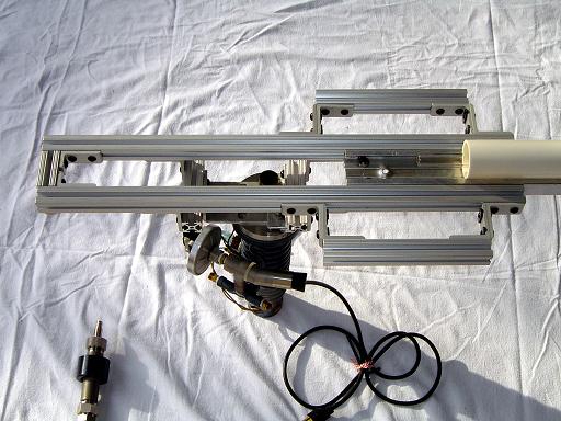
Beam line installed: Beam line slides into beam line shield, and diffusion pump mounts to the channels on the bottom of the frame. |
|
|
Vacuum hub mounted: Vacuum hub connects to the inlet of the diffusion pump. |
|
|
ZnS screen: ZnS screen glows when hit by accelerated electrons proving accelerator operation. ZnS from an old green screen computer monitor is coated onto a paper screen that is placed within the beam line |
|
|
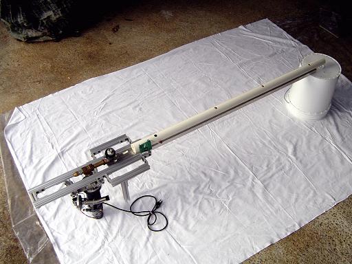
Accelerator Assembled:
|
By attempting to reproduce any experiments or devices listed on this domain in part or in whole, you agree to hold me harmless against any lawsuit or liability. Copyright © 1998 - 2005 by Andrew Seltzman. All rights reserved. |
|
| Contact me at: admin@rtftechnologies.org | |