IEC Fusion Reactor Mark 3 Fluorinert Cooled Grid
IEC Fusion Reactor Mark 3 Fluorinert Cooled Grid |
 |
 |
 |
 |
 |
 |
 |
Overview: The maximum input power to the central grid, and therefore the maximum fusion rate of the reactor, is limited by a condition called thermionic runaway. Above a certain input power threshold, any increase in grid temperature by ion bombardment increases the grids thermionic electron emission rate leading to greater neutral ionization rates within the reactor, further increasing ion bombardment heating until the grid melts. Grid heating also causes increased sputtering and sublimation rates of the surface atoms on a metal grid, leading to plasma impurities, grid erosion, and metal deposition on critical components such as high alumina ceramic feed throughs, insulators and view ports.For any given system this limits the fusion rate by restricting the maximum input voltage in two ways. First on a HV supply with adequate current capacity the input voltage must be limited to prevent thermionic runaway. Secondly, on a supply with lower current capacity, the electron emission rate from the grid will create a current load and accompanying voltage drop across the effective series impedance of the supply. Due the the exponential dependence of the deuterium cross section on ion energy, any voltage drop will come at significant cost of neutron output. No previously constructed IEC fusion system has used an actively cooled grid for several reasons, primarily the contact of the cooling medium with the high voltage grid. This requires the entire primary cooling loop to float at grid potential, usually several tens of kv, or the use of a non-conducting cooling medium. Further this requires the use of a high voltage dual liquid feed through, a component not commonly manufactured. The implementation of an actively cooled grid system will significantly
increase operation power and boost neutron fluxes by allowing higher input
voltages. Further, by reducing thermionic emission by cooling the central
grid, a lower current, higher voltage power supply can be used, increasing
ion energies and reducing construction cost. The decrease in thermionic
emission will decrease neutral ionization, allowing maximum accelerating
power to be imparted to the deuterium beams emitted from the ion injectors,
resulting in a sharper plasma focus with a quasi uniform ion energy distribution
increasing the probability of fast ion on fast ion collisions at near
head on angles. |
|
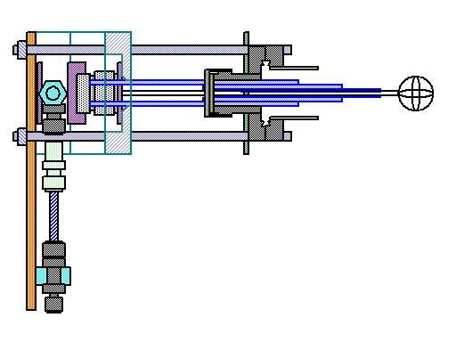 |
Grid Cooling Assembly (3/22/2007)
|
 |
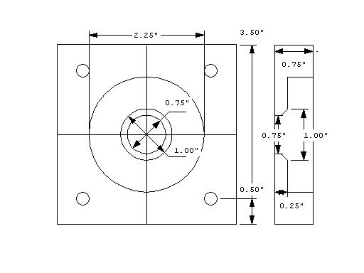
HDPE HV Insulator (9/30/2006) HV insulator CAD (same design as camera spacer) |
 |
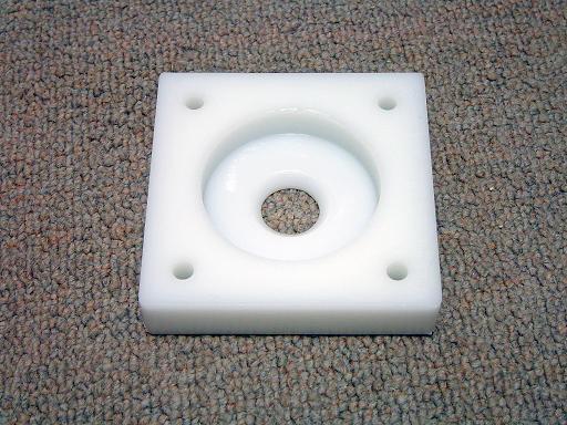
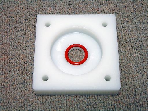
HDPE HV Insulator (9/30/2006) Side insulator for HV Fluorinert feed through. |
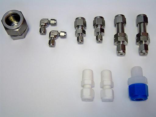 |
Grid cooling loop swagelok components (11/5/2006) Swagelok components for grid cooling loop. 0.75" cap, 1/16" elbows, 1/4" to 1/16" reducers, 1/8" to 1/4" bulkheads, teflon 1/4" npt to 1/4" tube, PFA 1/4" npt to 3/8" tube. |
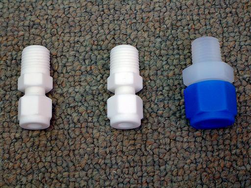 |
Box coolant and HV feed through swagelok components (11/5/2006) Teflon 1/4" npt to 1/4" tube, PFA 1/4" npt to 3/8" tube. |
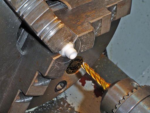 |
Boring fitting (11/5/2006) Teflon 1/4" npt to 1/4" tube fitting is not available in bored through form, fitting is bored through on the lathe using a 1/4" mill bit. |
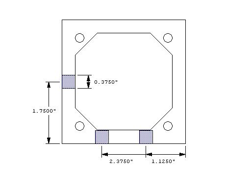 |
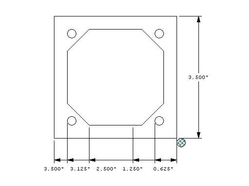
HV box hole CAD (11/5/2006) 3/8" holes are drilled into the HDPE HV box. |
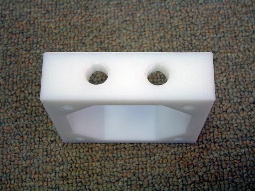 |
HV box taped holes (11/5/2006) Holes are taped with 1/4" npt threads. Dual holes are for coolant feed and return. |
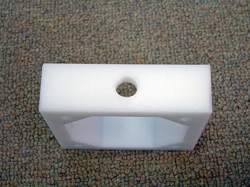 |
HV box taped holes (11/5/2006) Holes are taped with 1/4" npt threads. Single hole is for HV input. |
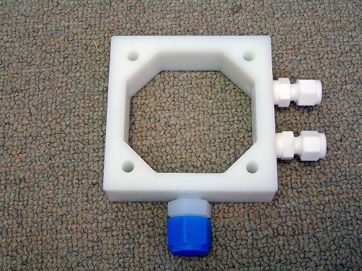 |
HV box with feed through fittings (11/5/2006) Non-conductive swagelok fittings are installed in the HV box. |
 |
Bulkhead mount (11/5/2006) Mounts bulkhead fittings to bottom support plate. |
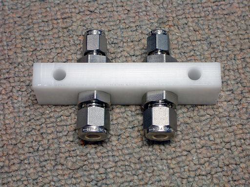 |
Bulkhead mount (11/5/2006) Bulkhead fittings mounted. |
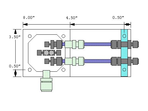 |
HV box feed through CAD (3/18/2007) Component placement in grid feed through box. |
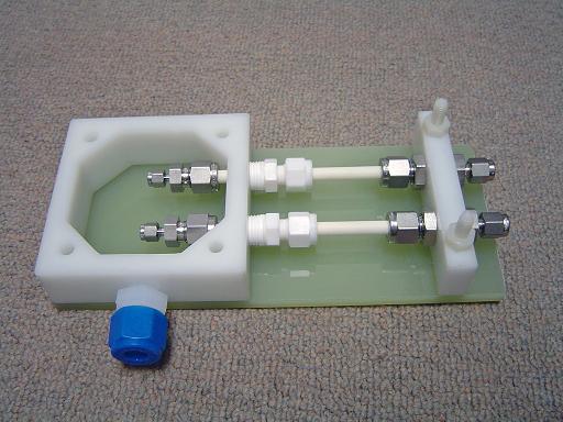 |
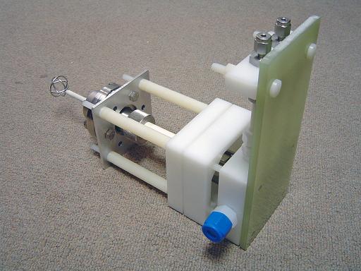
HV box with feed throughs installed (3/22/2007) Ceramic insulating breaks separate the swagelok fittings connected to the grid potential from the grounded fittings connected to the micropump. Base plate is machined out of G10/FR4 fiberglass. |
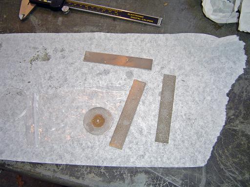 |
Diamond powder files (11/5/2006) Diamond powder files are used to polish ceramic. |
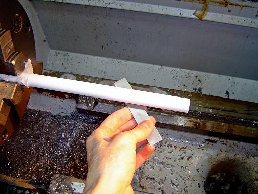 |
Polishing main feed through (11/5/2006) Ceramic tube will separate and shield HV grid fittings from grounded vacuum chamber. Ceramic tube is 0.75" OD, 0.5" ID. Tube is polished on lathe. |
 |
Ferrule plate and Compression plate (12/18/2006) Ferrule plate compresses ferules against the central grid tube exiting the 0.75" swagelok tube fitting and is held in place with the compression plate. |
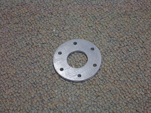 |
Compression plate (12/18/2006)
|
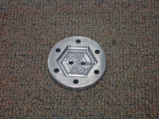 |
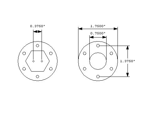
Hex plate (3/22/2007) Feed through holes are tapered to fit a 1/16" nylon swagelok front ferrule. When tightened down, the hex plate compresses the nylon ferrule which deforms such that the inside surface seals against the grid tubing and the back of the ferrule seals against the polished swagelok fitting. |
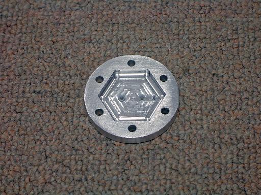 |
Hex plate (3/22/2007) With nylon ferrules inserted. |
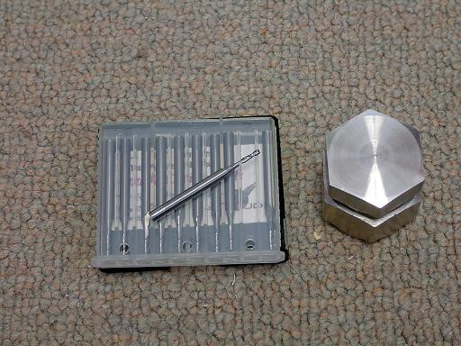 |
Swagelok fitting (12/21/2006)
|
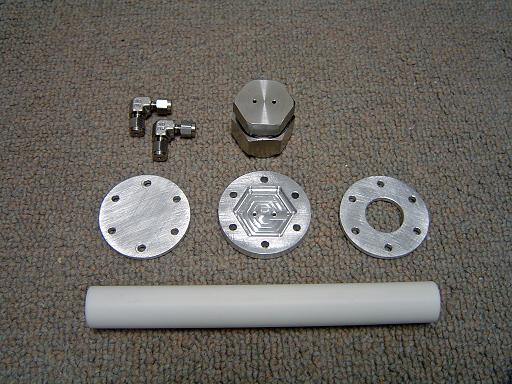 |
Feed through parts (12/21/2006)
|
 |
Swagelok captive(12/21/2006) Demonstrating precision fit in hex plate. |
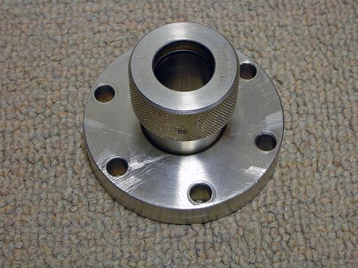 |
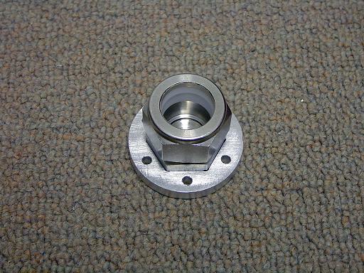
Conflat wilson seal (12/21/2006) Seals to high alumina feed through by compressing an o-ring against the surface of the rod. |
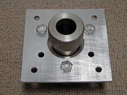 |
Conflat wilson seal (12/21/2006) Bolts to adaptor plate to mount support legs. |
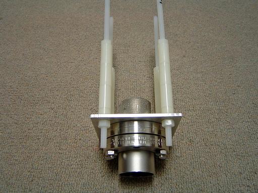 |
Conflat wilson seal (3/22/2007) With nylon standoff legs attached. Nylon threaded rods are 8" long and have 1/4-20 threading. Total standoff height from base of adaptor plate to end of retaining nut is 3.5" |
 |
HV box top plate (3/22/2007) |
 |
HV box top plate (3/22/2007) Tapered angle (45 degree) compresses o-ring against high alumina rod, increasing electrical insulation and sealing out water from condensing on chilled HV components. |
 |
HV box top plate (3/22/2007) O-ring in tapered area. |
 |
HV box top plate (3/22/2007) Mounted on standoff legs. |
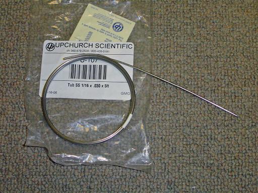 |
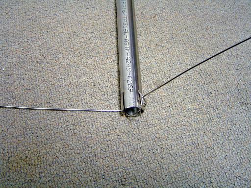
Grid tubing (3/22/2007) Spherical grid is wound out of 1/16" OD by 0.03" ID seamless 316SS tubing. 32" of tubing is required, 11" for each lag, and 10" for the sphere. |
 |
Grid winding (3/22/2007) Grid is wound around slotted 7/8" OD stainless tube. |
 |
Grid winding (3/22/2007)
|
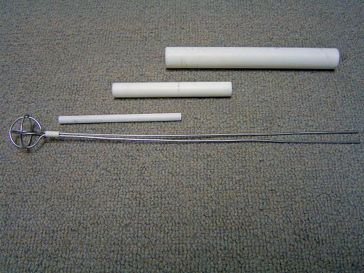 |
Grid ceramics (3/22/2007) 3/8" long dual bore ceramic tube (1/16"ID x2 3/16"OD) centers and supports coolant feeds in 4" long 3/16"ID 0.25"OD ceramic tube which fits into 4" long 0.25"ID 0.5"OD ceramic rod which is held securely in place in the 0.5"ID 0.75"OD main ceramic feed through |
 |
Grid ceramics (3/22/2007) Align over coolant feeds for support and electrical insulation. |
 |
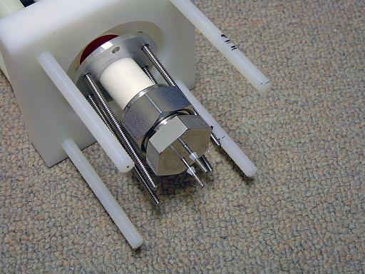
Grid feed through (3/22/2007) Grid is positioned within main ceramic feed through |
 |
Swagelok compression plate (3/22/2007) Slides over ceramic feed through within HV box. |
 |
Swagelok fitting (3/22/2007) Swagelok fitting with polished end cap seals to ceramic feed through with teflon ferrules. Nylon front ferrules are positioned on coolant feeds. |
 |
HEX plate (3/22/2007) Hex plate compresses nylon ferrules against coolant feeds and swagelok fitting. |
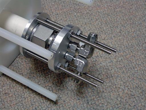 |
Swagelok elbows (3/22/2007) Swagelok elbows seal to coolant feeds with nylon ferrules to allow grid to easily be removed and exchanged. |
 |
Swagelok adaptors (3/22/2007) 1/16" tubing as used to connect elbows to adaptors for connecting to 1/4" ceramic coolant feedthroughs. Elbows and adaptors have standard stainless ferrules for connecting to external 1/16" tubing. Adaptors have teflon ferrules for connecting to high alumina tubes. |
 |
Elbow compression plate (3/22/2007) Prevents elbows with nylon ferules from slipping off of grid coolant feeds under high pressure. Compression plate screws pass through the notch in the swagelok adaptor fitting between the body and the end cap to prevent them from slipping |
 |
HV connector (3/22/2007) Electrically connects to aluminum plate. |
 |
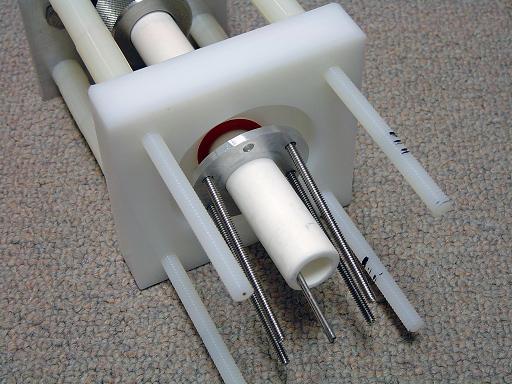
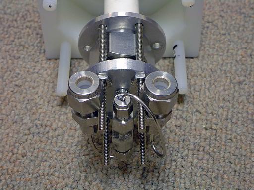
Coolant feedthroughs (3/22/2007) 4.5" long high alumina tubes drop through the bored through teflon swagelok fittings into the swagelok adaptors below. Teflon swagelok fittings seal against the ceramic tubes to add electrical insulation and seal out condensation. |
 |
Base plate (3/22/2007) Base plate drops in from above connecting ceramic rods to bulkhead feedthroughs and rigidly holding the base structure in place and providing insulation for the bottom of the HV box. |
 |
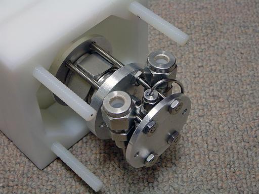
Lower bolts (3/22/2007) The entire inner assembly (including the o-ring) is 1/16" longer then the interior of the HV box. Tightening the lower bolts compresses the o-ring against the box top and the ceramic feed through rod. |
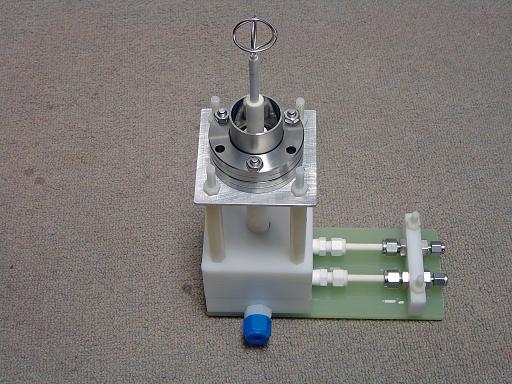 |
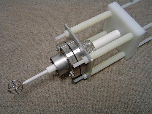
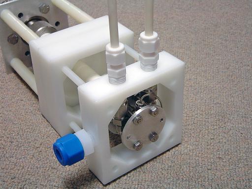
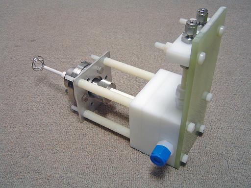
Completed assembly (3/22/2007)
|
 |
HV shield tube mount (10/13/2007) Mounts a teflon tube to reactor frame. |
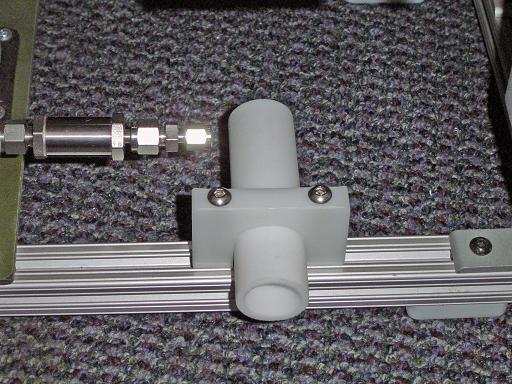 |
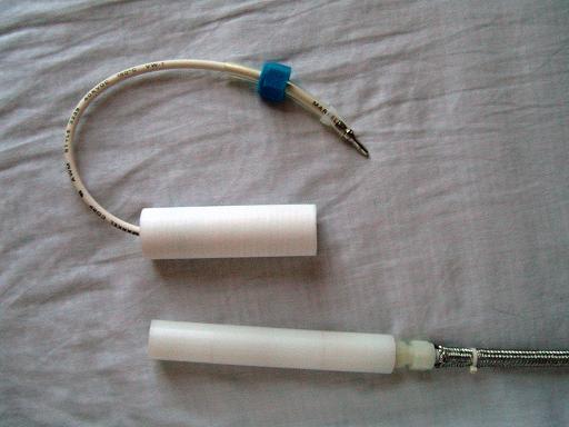
HV shield tube (10/13/2007) Provides additional insulation to the HV input line. |
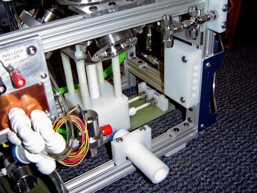 |
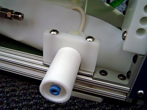
Cooled grid installed (1/05/2008) Cooled grid installed in reactor. |
 |
Cooled grid installed (1/05/2008) Cooled grid installed in reactor. |
 |
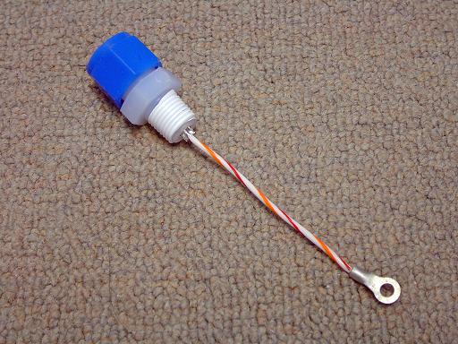
HV socket (2/06/2007) Connects reactor to x-ray transformer. |
 |
HV plug (2/06/2007) Connects reactor to x-ray transformer. |
 |
HV socket / plug parts (2/06/2007) Components for socket and plug. |
 |
HV socket / plug parts (2/06/2007) Power connected through shielded banana jack. |
 |
HV socket / plug assembled (2/06/2007) Assembled plug and socket. |
 |
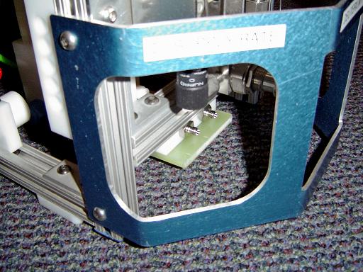
HV socket mounted (2/06/2007) Assembled socket mounted on reactor. |
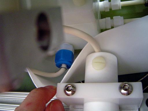 |
HV socket wiring (2/06/2007) Socket wired to cooled grid. |
| Useful links:http://www.fusor.net/ Open Source Fusion Research Consortium. | |
By attempting to reproduce any experiments or devices listed on this domain in part or in whole, you agree to hold me harmless against any lawsuit or liability. Copyright © 1998 - 2005 by Andrew Seltzman. All rights reserved. |
|
| Contact me at: admin@rtftechnologies.org | |