IEC Fusion Reactor Mark 3 Ion Collector Array
IEC Fusion Reactor Mark 3 Ion Collector Array |
 |
 |
 |
 |
 |
 |
 |
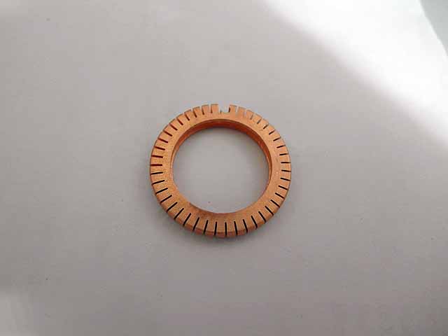
Overview: A segmemted ion collector is added to the fusor grid to allow measurement of ion bombardment intensity vs position. Ion collector was machined out of a copper shim on a 5-axis CNC mill
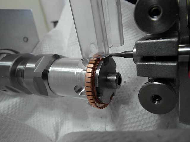
Rough estimate for thermal resistance of copper standoffs on ion collector: Aat 16mTorr and 13k, ~5ma of current will be drawn from the grid power supply yielding 65W total into the grid (assuming 100% electrical power disipated into grid). The 3 ring grid will have 12 segments, so 5.4W/segment. With a 10 element ion collector array mounted onto a given segment, 0.54w/collector. Assuming equal power dissipation into each collector, for a 25C temperature rise for wach collector the standoff should have ~50C/W thermal resistance. Assuming thermal conductivity for copper K=400 w*m^-1*k^-1, a 1/16"(2.5mm) wide, 1/16"(2.5mm) long standoff should have a 0.05mm thickness. The final design had a 0.2mm thickness with a 0.028"(1.1mm) hole (#70 drill) drilled through the width-length plane.
|
|
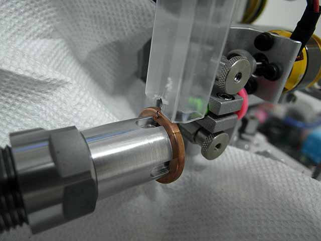 |
Ion Collector (9/19/2014) Copper shim mounted on holder in a-axis chuck, b-axis rotated 90 degrees, milling observation hole through thickness |
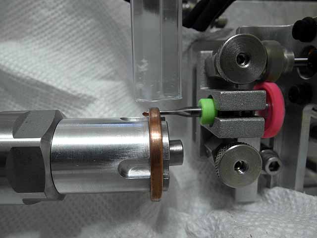 |
Ion Collector (9/19/2014) Copper shim mounted on holder in a-axis chuck, b-axis rotated 90 degrees, milling observation hole through thickness |
 |
Ion Collector (9/19/2014) Copper shim mounted on holder in a-axis chuck, b-axis rotated 90 degrees, milling observation hole through thickness |
 |
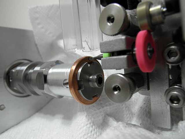
Ion Collector (9/19/2014) Notch milled in front of face, using slotting saw to mill out collector segments. Slot is 0.01" thick. |
 |
Ion Collector (9/19/2014) Notch milled in front of face, using slotting saw to mill out collector segments. Slot is 0.01" thick. |
 |
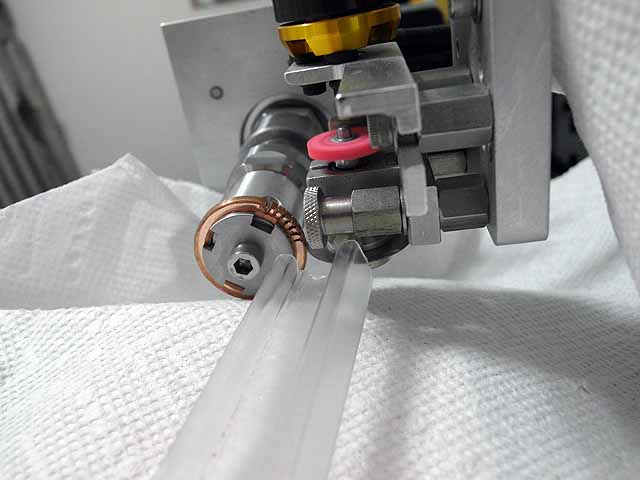
Ion Collector (9/19/2014) Several collector segments milled out |
 |
Ion Collector (9/19/2014) Several collector segments milled out |
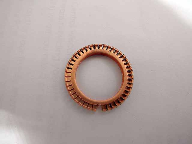 |
Ion Collector (9/19/2014) All collector segments milled out |
 |
Ion Collector (9/19/2014) All collector segments milled out |
 |
Ion Collector (9/19/2014) All collector segments milled out |
 |
Ion Collector (9/19/2014) All collector segments milled out, mounted in a-axis holder |
 |
Ion Collector (9/19/2014) Milling slot in other face leaving ~0.02mm thickness on the standoffs. |
|
Ion Collector (9/19/2014) Milling slot in other face leaving ~0.02mm thickness on the standoffs. |
 |
Ion Collector (9/19/2014) Milling slot in other face leaving ~0.02mm thickness on the standoffs. |
 |
Ion Collector (9/19/2014) Cutting collector arrays apart |
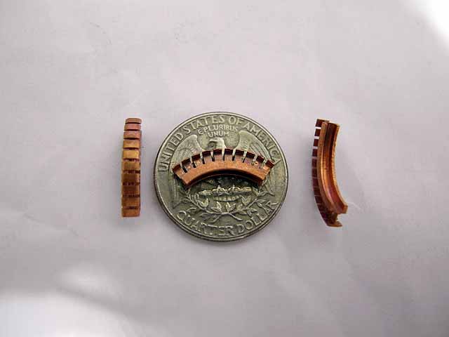 |
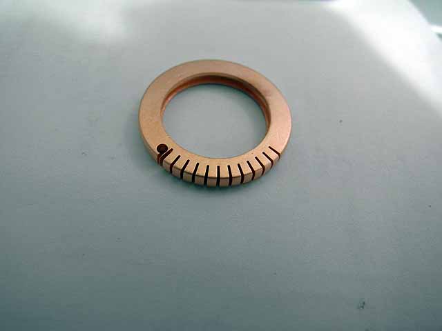
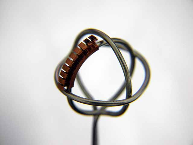
Ion Collector (9/19/2014) Arays were acid etched in brite dip to remove burs. Ion collector arrays on quarter for scale. |
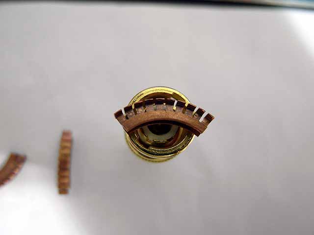 |
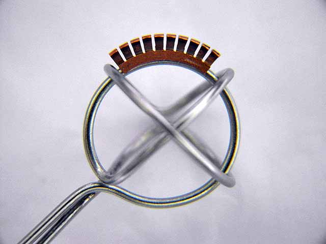
Ion Collector (9/19/2014) Ion collector arrays on BNC fitting for scale. |
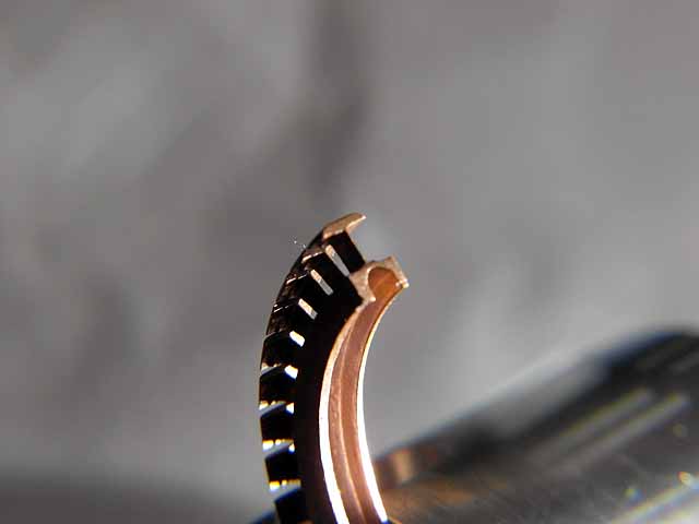 |
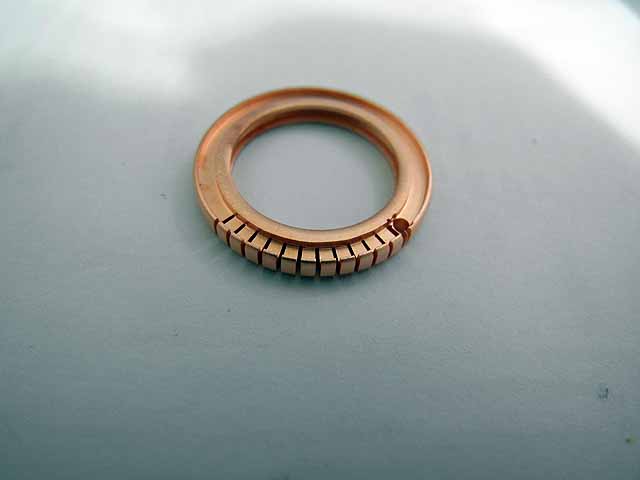
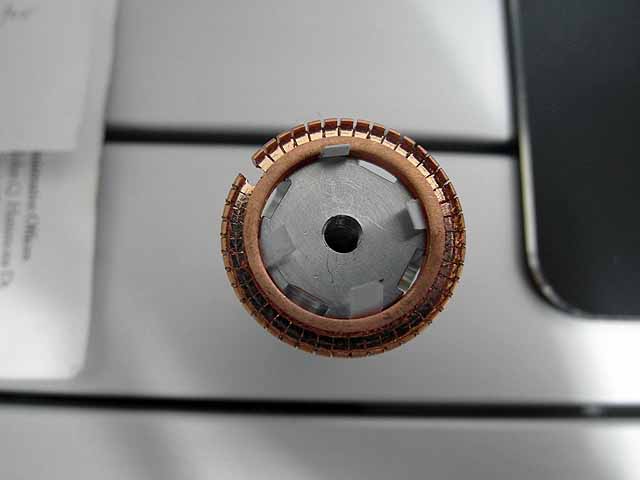
Ion Collector (9/19/2014) Angled view of collector |
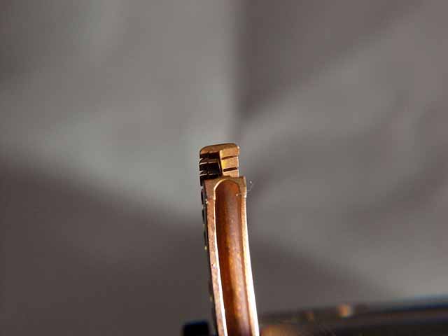 |
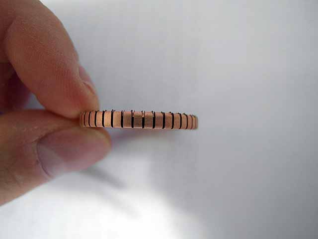
Ion Collector (9/19/2014) View showing standoff thickness |
 |
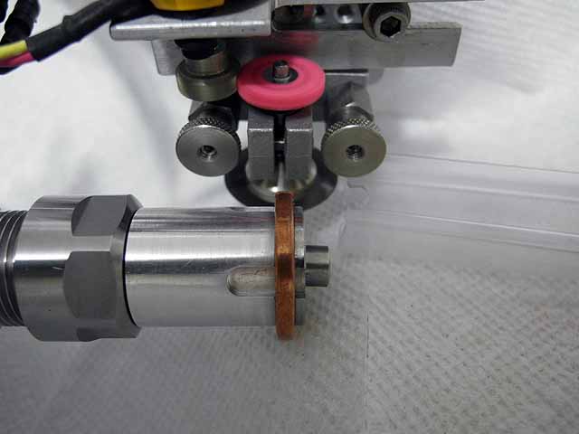
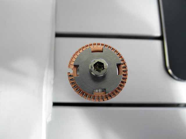
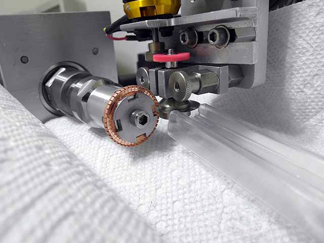
Ion Collector (9/19/2014) Test fit on test grid |
 |
Ion Collector (9/19/2014) Test fit on test grid |
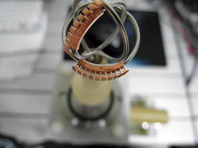 |
Ion Collector (9/19/2014) Holes drilled in segmant face for increaced thermal resistance, ion collectors mounted on fusor grid. |
 |
Ion Collector (9/19/2014) Holes drilled in segmant face for increaced thermal resistance, ion collectors mounted on fusor grid. |
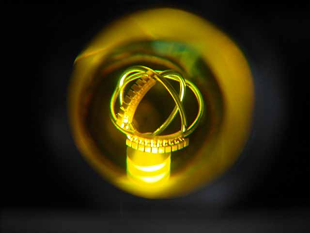 |
Ion Collector (9/19/2014) Grid mounted on fusor. |
 |
Ion Collector (9/19/2014) Grid HV off |
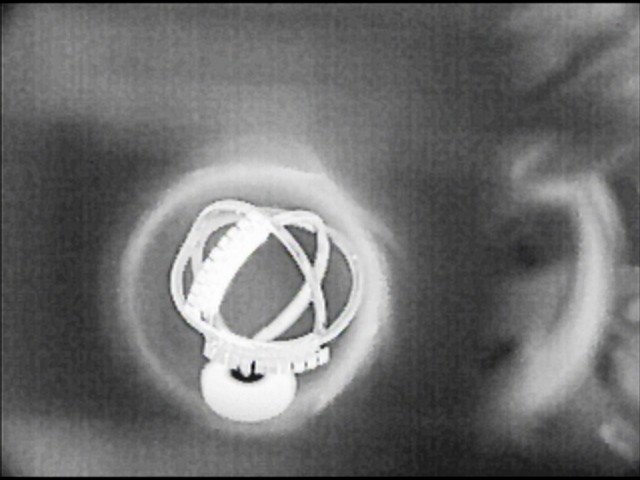 |
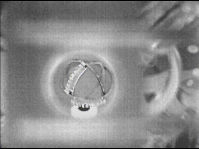
Ion Collector (9/19/2014) Grid HV on |
| Useful links:http://www.fusor.net/ Open Source Fusion Research Consortium. | |
By attempting to reproduce any experiments or devices listed on this domain in part or in whole, you agree to hold me harmless against any lawsuit or liability. Copyright © 1998 - 2005 by Andrew Seltzman. All rights reserved. |
|
| Contact me at: admin@rtftechnologies.org | |